Supercharge Your Innovation With Domain-Expert AI Agents!

Magnetic sensor device with robust signal processing

A magnetic sensor and sensor technology, applied in the direction of measuring devices, magnetic performance measurement, instruments, etc., can solve the problem of very sensitive parameter changes

Inactive Publication Date: 2009-10-21
KONINKLIJKE PHILIPS ELECTRONICS NV
View PDF5 Cites 4 Cited by
  • Summary
  • Abstract
  • Description
  • Claims
  • Application Information

AI Technical Summary

Problems solved by technology

[0003] A problem with magnetic biosensors of the aforementioned kind is that the measurements are very sensitive to uncontrollable parameter variations in applied excitation and sensor current, sensor gain, temperature, etc.

Method used


Image

  • Magnetic sensor device with robust signal processing
  • Magnetic sensor device with robust signal processing
  • Magnetic sensor device with robust signal processing

Examples


Embodiment Construction

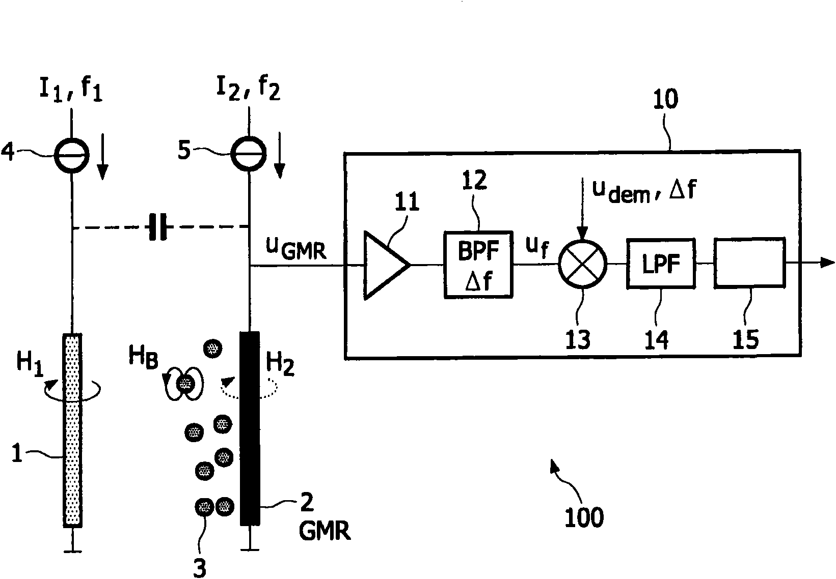
[0035] figure 1A microelectronic magnetic sensor device according to the invention is illustrated for the detection of magnetically interacting particles, for example superparamagnetic beads 3 , in a sample chamber in a particular application as a biosensor. Magnetoresistive biochips or biosensors have desirable properties for biomolecular diagnostics in terms of sensitivity, characteristics, binding, ease of use, and cost. Examples of such biochips are described in WO2003 / 054566, WO 2003 / 054523, WO 2005 / 010542A2, WO2005 / 010543A1 and WO 2005 / 038911A1, which are incorporated herein by reference.

[0036] figure 1 The illustrated magnetic sensor device 100 comprises at least one magnetic field generator, which can be realized as a wire 1 on a substrate (not shown), or which can be located outside the sensor chip. Field generator 1 by having a first frequency f 1 The sinusoidal excitation current I 1 Driven by a current source 4 for generating an alternating external magnetic...


PUM


Abstract

The invention relates to a magnetic sensor device (100) comprising a magnetic field generator (1) driven with an excitation current of a first frequency (f1) and a magnetic sensor element (e.g. a GMR sensor (2)) driven with a sensor current (I2) of a second frequency (f2) for measuring reaction fields (HB) generated by magnetized particles (3). In an associated evaluation unit (10), a reference component (uQ) of the measurement signal (uGMR) is separated that depends on the excitation current (I1) and the sensor current (I2) but not on the presence of magnetized particles (3). The reference component (uQ) may particularly be produced by a combination of the self- magnetization (H2) of the magnetic sensor element (2) and cross-talk related currents. The reference component (uQ) may be isolated based on its phase with respect to a particle-dependent component of the measurement signal (uGMR) or based on its scaling with one of the current frequencies. Monitoring of the reference component (uQ) reveals variations in operating conditions, for example in the sensor gain, that can be used to calibrate the measurement results.

Description

field of invention [0001] The present invention relates to methods and magnetic sensor devices for detecting magnetized particles in a sample chamber. And it involves the use of such devices. Background technique [0002] Magnetic sensor devices are known from WO 2005 / 010543 A1 and WO 2005 / 010542 A2, which can be used, for example, in microfluidic biosensors for detecting (eg biological) molecules labeled with magnetic beads. The microsensor device is provided with an array of sensor cells comprising wires for generating a magnetic field and giant magnetoresistive devices (GMR) for detecting stray fields generated by magnetic beads. At that time, the resistance of the GMR indicates the number of beads near the sensor unit. [0003] A problem with magnetic biosensors of the aforementioned kind is that the measurements are very sensitive to uncontrollable parameter changes in applied excitation and sensor current, sensor gain, temperature, and so on. Contents of the invent...

Claims


Application Information

Patent Timeline
IPC IPC(8): G01N33/543G01R33/09G01R33/12
CPCG01R33/093G01R33/1269B82Y25/00
Inventor J·维恩T·P·H·G·詹森B·M·德博尔J·A·H·M·卡尔曼
Owner KONINKLIJKE PHILIPS ELECTRONICS NV
Features
  • R&D
  • Intellectual Property
  • Life Sciences
  • Materials
  • Tech Scout
  • Unparalleled Data Quality
  • Higher Quality Content
  • 60% Fewer Hallucinations
Learn More