Method for fluidizing and coating ultrafine particles, device for fluidizing and coating ultrafine particles

a technology of fluidizing and coating ultrafine particles, applied in the direction of watering devices, coatings, applications, etc., can solve the problems of affecting the performance of the electrolyte-based system, so as to prevent unwanted side reactions, prevent unwanted reactions of exposed particle surfaces, and improve performan

Active Publication Date: 2013-08-08
UCHICAGO ARGONNE LLC
View PDF1 Cites 13 Cited by
  • Summary
  • Abstract
  • Description
  • Claims
  • Application Information

AI Technical Summary

Benefits of technology

[0017]Still another object of the present invention is to provide a method for coating porous particles, each particle which is less than about 50 microns in diameter and typically below about 20 microns in diameter. A feature of the method is the use of a standing wave to keep the particles (including porous materials) homogeneously fluidized. An advantage of the invention is that it renders all of the particles accessible to coating moieties such that substantially the entire surface of the porous material is coated to prevent unwanted reactions of exposed particle surface with the environment of the particle. In an embodiment of the invention, the standing wave comprises the coating moieties some of which eventually form the coating on the fluidized substrates.
[0018]Another object of the present invention is to provide a conformal coating onto a substrate. A feature of the invention is that the substrate comprises a particle which measures less than about 20 μm in diameter, wherein the substrate is completely encapsulated in an oxide via atomic layer deposition. An advantage of the invention is that the resulting conformal and pin-hole free coating, with both film thickness and composition precisely controlled, exhibits superior performance compared to coated substrates produced via random processes.
[0019]Yet another object of the present invention is providing optimized electrode-electrolyte interfaces in batteries. A feature of the invention is that cathodes are coated (no thicker than 20 nanometers, and preferably from about 0.1 to 10 nanometers) with material which prevents unwanted side reactions such as migration of metal ions. An advantage of the invention is the preservation of recharging capacities.
[0020]Briefly, the invention provides a method for dispersing particles within a reaction field, the method comprising confining the particles to the reaction field using a standing wave.
[0021]The invention also provides a system for coating particles, the system comprising a reaction zone; a means for producing fluidized particles within the reaction zone; a fluid to produce a standing wave within the reaction zone; and a means for introducing coating moieties to the reaction zone. In an embodiment of the invention, the coating moieties comprise at least a portion of the standing wave.
[0022]The invention also provides a method for coating particles, the method comprising fluidizing the particles, subjecting the particles to a standing wave; and contacting the subjected particles with a coating moiety.

Problems solved by technology

These sales will be concomitant with the attainment of higher efficiencies.
Problems abound for electrolyte-based systems.
For example, structures physically immersed into the electrolyte are inevitably attacked by the surrounding electrolyte though redox chemical reactions.
This significantly shortens the battery life and, even worse, creates explosion hazards.
Also, the sought-after high voltages of advanced batter systems often exceed the electrochemical resistance of electrolyte oxidation; as such, irreversible capacity degradation occurs whereby the electrolyte is compromised.
Specifically, at target voltages and the accompanying temperature increases, the manganese in the spinels plate on the anodes, thereby decreasing recharge capacity.
However, in electrochemical applications, the aforementioned degradation of electrodes and electrolyte is problematic.
However, most of these techniques are relegated to situations where the geometries of the host objects are in flat, or large particles, and particularly, the uniformity and layer thickness of the coating layers are not concerns.
The above-mentioned state of the art coating techniques fall short of these objectives.
However, particles with diameters less than about 20 micrometers (i.e. microns or μm) show strong flow instability when placed in a flowing medium, such as a fluidized bed, for mixing.

Method used


Image

  • Method for fluidizing and coating ultrafine particles, device for fluidizing and coating ultrafine particles
  • Method for fluidizing and coating ultrafine particles, device for fluidizing and coating ultrafine particles
  • Method for fluidizing and coating ultrafine particles, device for fluidizing and coating ultrafine particles

Examples


example 1

Fluidization Example 1

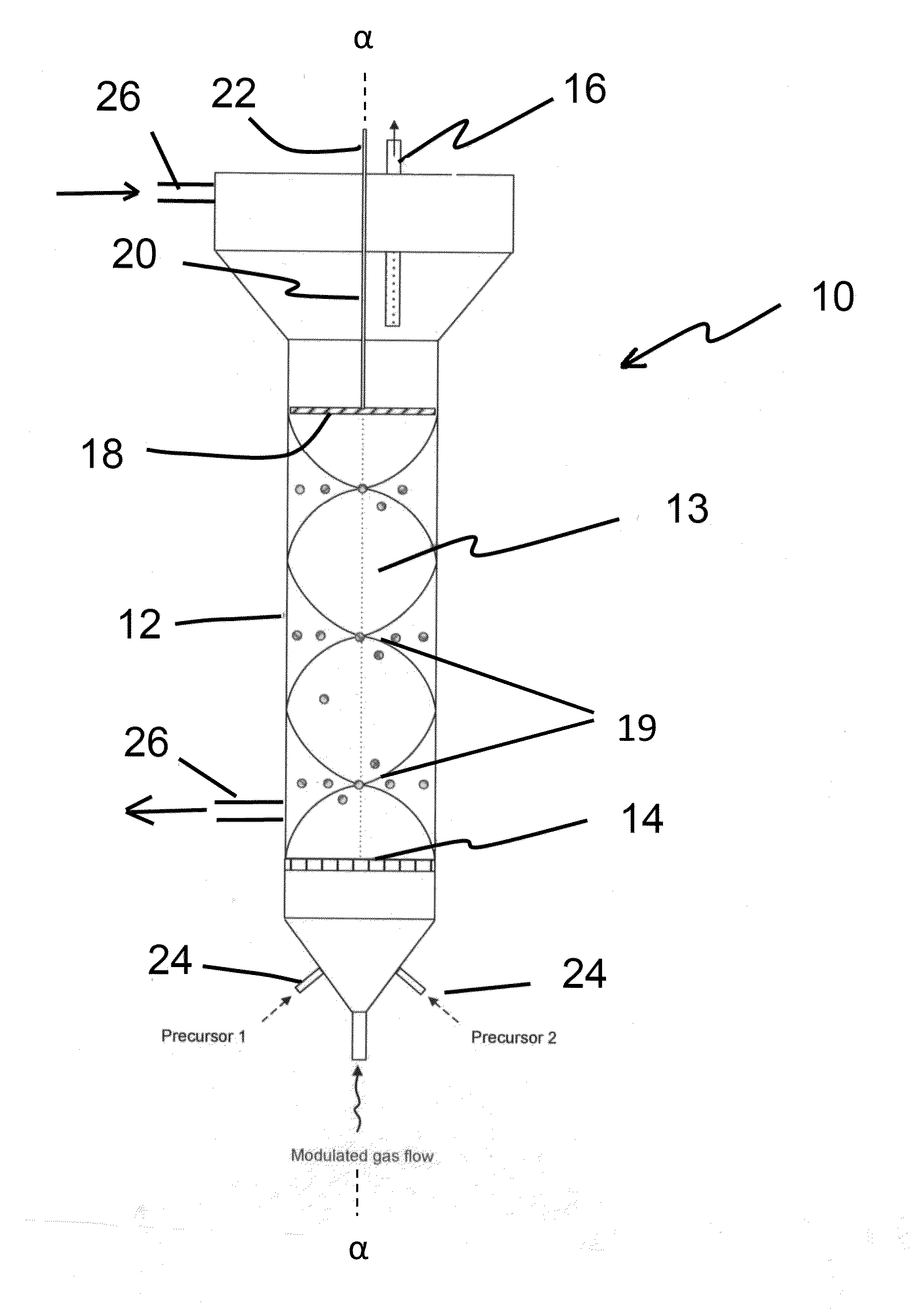
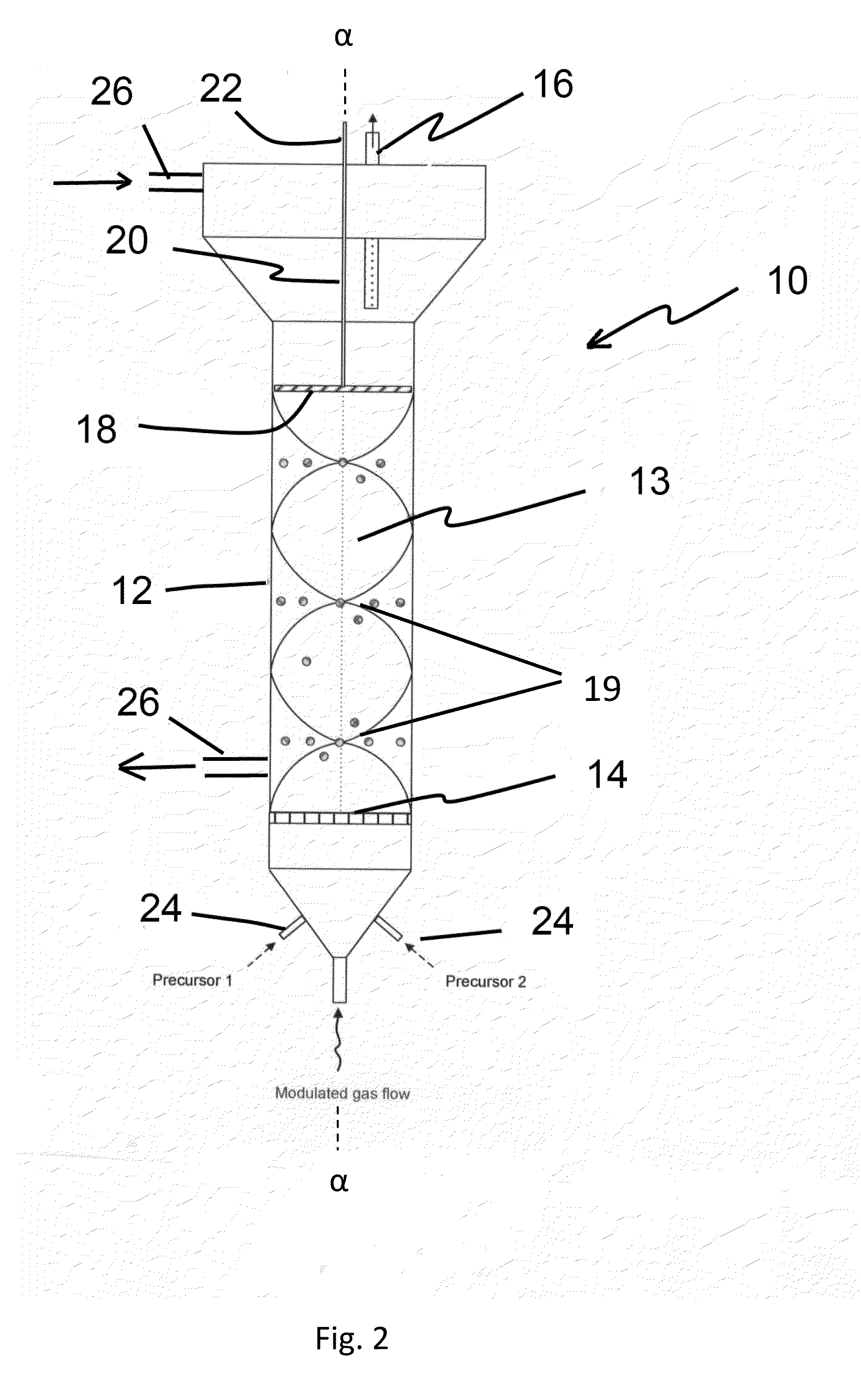
[0107]Li-ion cathode particles, having a means size of between about 5 and 10 microns, were homogenously fluidized. The tap density was about 2 to 2.8 g / cm3. (Tap density is the powder density measured after the powders are tapped for a certain period of time while residing in a graduated cup, cylinder, container or other volume measuring means. The wave frequency was about 3 Hz using about 12 pounds per square inch (psi) inlet N2 pressure and atmospheric bed pressure. The fluidization occurred in a laboratory-scale sized fluidized bed having approximately a 4 centimeter outside diameter. Both atmospheric and vacuum conditions produced suitable alumina coatings, as depicted in FIG. 4 and discussed supra. Stable fluidization endured until the wave media feed was stopped.

example 2

Fluidization Example 2

[0108]LiNi0.5Mn1.5O4 particles of approximately 5 to 10 microns were fluidized. The wave frequency was about 3 Hz. Approximately 12 psi nitrogen press and a vacuum bed pressure (2 torr) was utilized. (Typically, frequencies between about 1 and 10 Hz are preferred.) The inventor discovered that stable fluidization occurs under both atmospheric and vacuum conditions for several hours until the gas flow is terminated.

example 3

[0109]Ultrafine particles are also partially homogenized via ultrasound waves. In this example, iron powder between about 1 to 10 microns in particle diameter are fluidized using 250 kHz frequencies, and at about 170 dB in sound intensity. This sound intensity represents the amplitude of the ultrasonic wave. Generally, between 100 dB and 200 dB are suitable acoustic frequencies for ultrasonic mixing of the particles. Compared to fluid modulation discussed supra, the sound wave approach imparts lower pressure intensities.

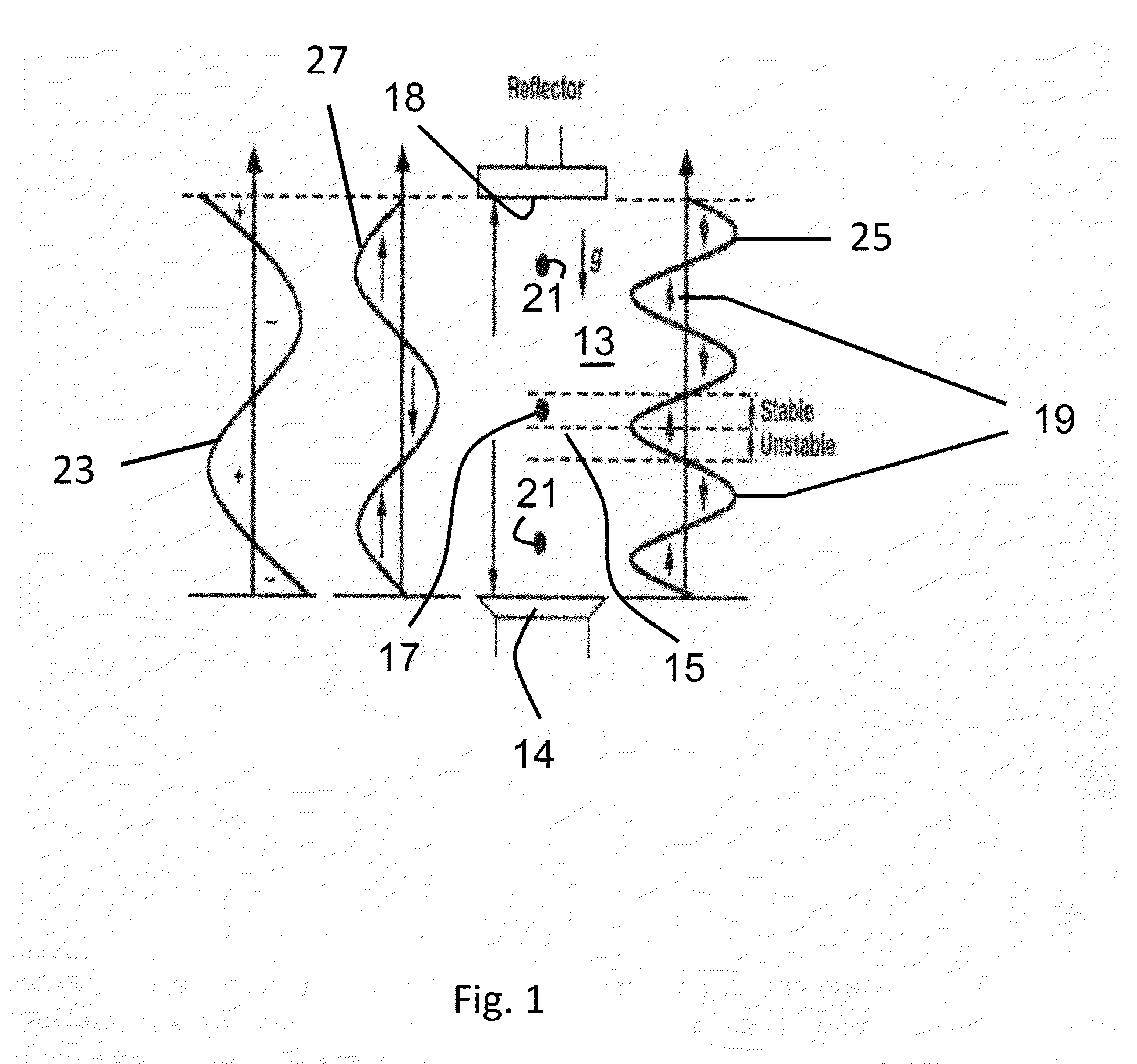
[0110]In all examples, a wave reflector is utilized. Also in all examples, evidence of homogenous dispersion was an observed by either visualizing the powder fluidization (by looking through the walls of the reactor container when quartz reactors are utilized), by noting pressures drop across the fluidized bed, (which result from a suspended bed weight), by calculating the suspended particle density, or a combination of these means. The process continued until the wa...


PUM

PropertyMeasurementUnit
diameteraaaaaaaaaa
diameteraaaaaaaaaa
diameteraaaaaaaaaa

Abstract

The invention provides a method for dispersing particles within a reaction field, the method comprising confining the particles to the reaction field using a standing wave. The invention also provides a system for coating particles, the system comprising a reaction zone; a means for producing fluidized particles within the reaction zone; a fluid to produce a standing wave within the reaction zone; and a means for introducing coating moieties to the reaction zone. The invention also provides a method for coating particles, the method comprising fluidizing the particles, subjecting the particles to a standing wave; and contacting the subjected particles with a coating moiety.

Description

CONTRACTUAL ORIGIN OF THE INVENTION[0001]The U.S. Government has rights in this invention pursuant to Contract No. DE-AC02-06CH11357 between the U.S. Department of Energy and UChicago Argonne, representing Argonne National Laboratory.BACKGROUND OF THE INVENTION[0002]1. Field of the Invention[0003]This invention relates to the production of coatings onto particles, and more particularly, this invention relates to the production of conformal coatings onto particulate substrates.[0004]2. Background of the Invention[0005]Optimization of reaction surfaces is key to more efficient chemical reactions. The more controlled the catalytic interface, the more leveraged are the effects of electron confinement.[0006]Well-controlled reaction surfaces would increase efficiencies in catalysis, energy production and energy storage. In the lithium ion battery market alone, the global U.S. dollar sales are projected to double by 2016. These sales will be concomitant with the attainment of higher effici...

Claims


Application Information

Patent Timeline
Patent Type & Authority Applications(United States)
IPC IPC(8): B05D7/00B05C13/02B05B17/00
CPCB01J2/006B05C13/02B01J2/16C23C16/45502C23C16/442C23C16/4417B05C19/02B05C19/06B05D1/24
Inventor LI, JIELIU, YUNG Y.
Owner UCHICAGO ARGONNE LLC
Why Eureka
Try Eureka