Illumination module and method

A technology of light and optical components, applied in the field of lighting units, can solve the problems of low array efficiency

Inactive Publication Date: 2009-10-21
THOMSON LICENSING SA
View PDF5 Cites 0 Cited by
  • Summary
  • Abstract
  • Description
  • Claims
  • Application Information

AI Technical Summary

Problems solved by technology

Therefore, regardless of the number of LEDs employed, the effi...

Method used


Image

  • Illumination module and method
  • Illumination module and method
  • Illumination module and method

Examples


Embodiment Construction

[0018] In the embodiments shown in the drawings, specific terminology is employed for the sake of clarity. However, the invention is not intended to be limited to the specific terms so selected, and it is to be understood that each specific element includes all technical equivalents which operate in a similar manner to accomplish a similar purpose. Additionally, features and procedures whose implementations are already known by those of ordinary skill in the art are omitted for the sake of brevity.

[0019] figure 2

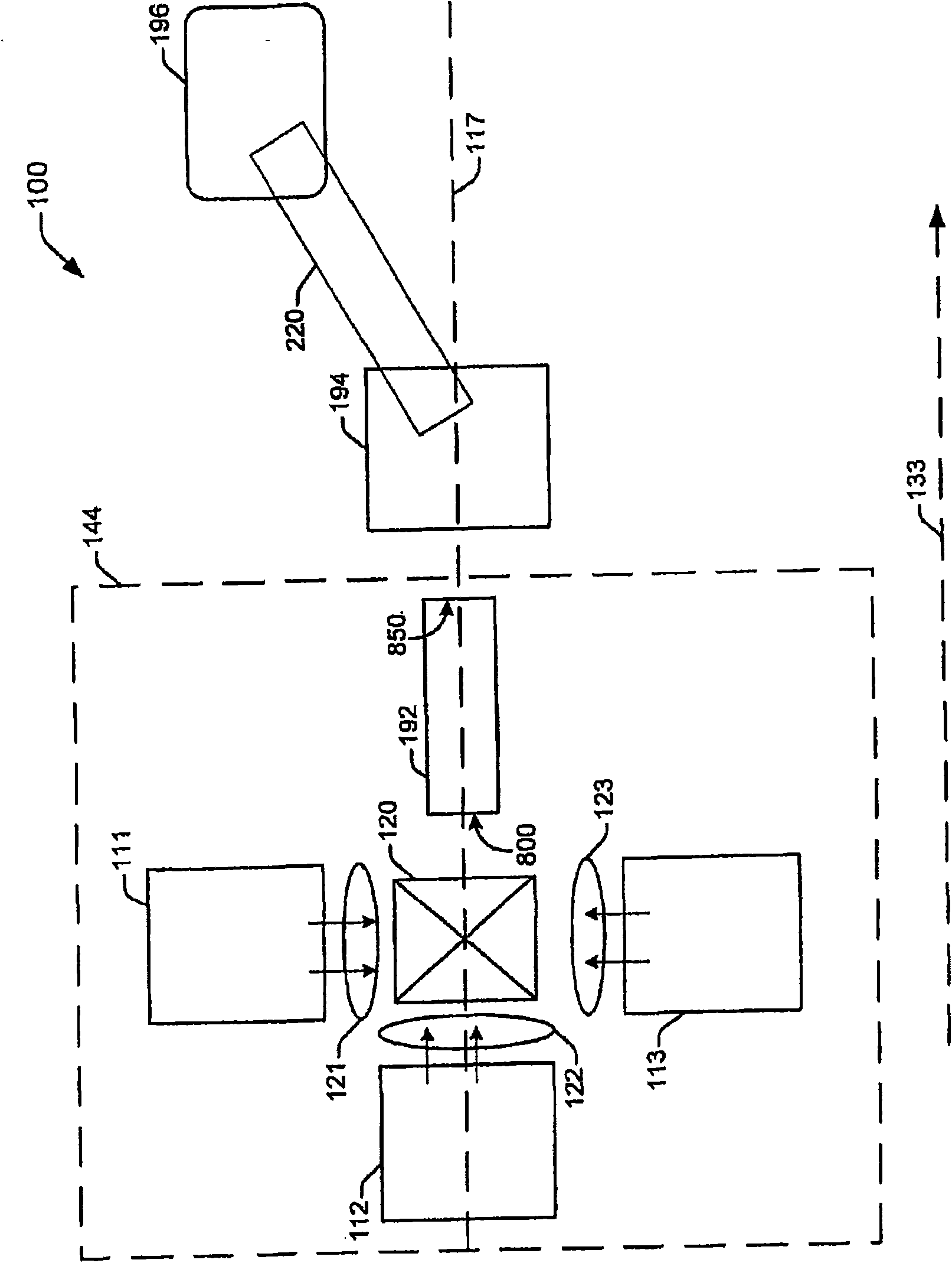
[0020] figure 2 is a block diagram including the optical components of the spatial light modulation (SLM) display system 100 . System 100 relies on a multiple light source approach. In this approach, there is one light source for each color (red, green and blue). The multiple light source method produces multiple images with each light source. The images are combined to produce a color display.

[0021] The display system 100 includes illumination optics...


PUM


Abstract

An illumination unit provides light for a projection display system. The illumination unit includes a light guide defined by an entry angle. A light source 200 provides emitted light according to a characteristic radiation pattern. A lens arrangement including at least one lens collects a portion of the light emitted through the radiation pattern and focuses the collected light so as to reach thelight guide within the entry angle 215. The portion of emitted light that is collected, and the collected light that enters the light guide within the angle, cooperate to maximize a percentage of thelight source's emitted light that is usable by the projection optics portion of the system.

Description

technical field [0001] The invention relates to a lighting unit for guiding light from a lighting unit to an image projection device. Background technique [0002] A spatial light modulation (SLM) display system is a system that uses light reflected or transmitted by a single element of a spatial light modulator, sometimes called an imager, to generate a displayed image. One type of spatial light modulator is a digital mirror device (DMD). SLM display systems are known, which include a DMD, eg commercially available from the company Texas Instruments under the trademark DLP (Digital Light Processing). [0003] FIG. 1 shows a conventional SLM projection display system 10 . The system 10 includes a light source 11 . Light source 11 generally comprises an arc lamp emitting white light. White light from light source 11 travels from light source 11 to DMD 19 along an optical path defining illumination subsystem 21 . The beam path of the illumination subsystem 21 extends alon...

Claims


Application Information

Patent Timeline
IPC IPC(8): G02B19/00H01L33/00H04N5/74H04N9/31
CPCG02B19/0061H04N9/3197G02B19/00G02B6/4298G02B19/0028H04N9/3152H01L33/00
Inventor 埃斯蒂尔·T·豪尔
Owner THOMSON LICENSING SA
Why Eureka
Try Eureka