
Novel progressive safety tongs

A progressive, safety gear technology, applied in elevators, elevators in buildings, transportation and packaging, etc., can solve the problems of wire rope breakage, high production costs, and large space occupation of speed governors, and achieve simplified structure and structure Compact and easy to install

Inactive Publication Date: 2009-10-28
HITACHI ELEVATOR CHINA
View PDF0 Cites 30 Cited by
  • Summary
  • Abstract
  • Description
  • Claims
  • Application Information

AI Technical Summary

Problems solved by technology

The safety lifting device is generally composed of a spring and a lifting rod, and is installed on the beam on the top of the car or on the bottom beam of the car. action
If the pressure rope force of the speed limiter is not enough, or the wire rope of the speed limiter is broken, accidents are likely to occur
In addition, because the sheave of the individual speed limiter needs to provide a certain rope clamping force, the performance requirements of the sheave are very high, and related parts must be installed, resulting in higher production costs.

Method used


Image

  • Novel progressive safety tongs
  • Novel progressive safety tongs
  • Novel progressive safety tongs

Examples


Embodiment Construction

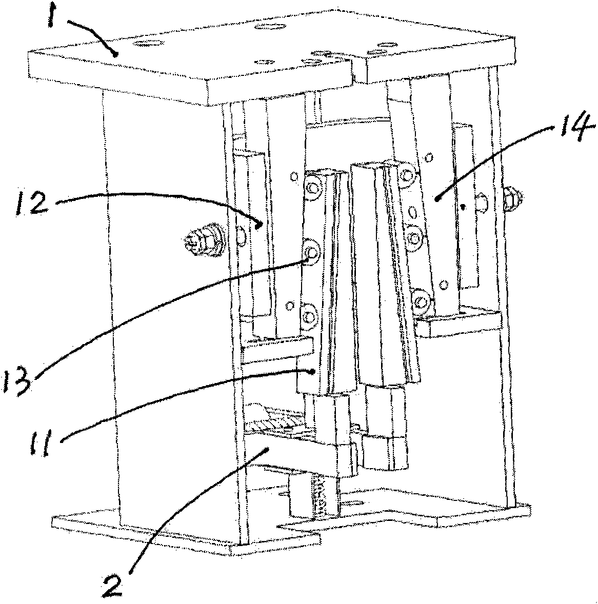
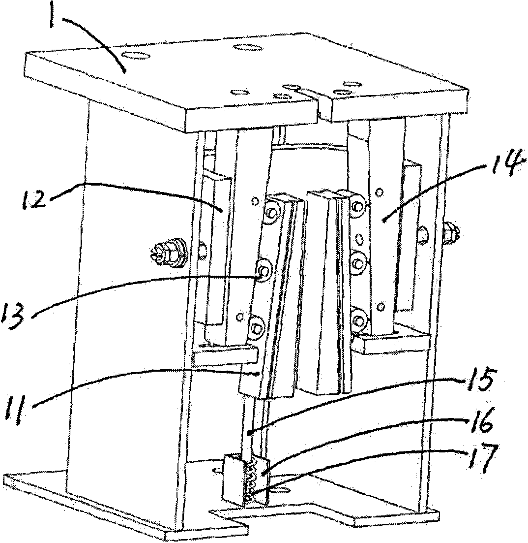
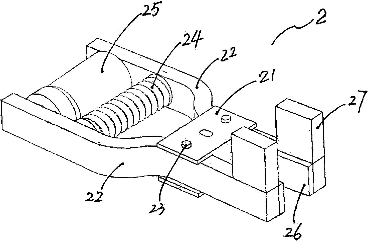
[0021] Such as Figure 1 to Figure 3 As shown, the novel progressive safety gear of the present invention has a pliers body 1, and a movable wedge 11, a U-shaped spring 12, a ball 13, a guide block 14 and a pushing mechanism 2 are installed in the pliers body 1. The pushing mechanism 2 is arranged in the caliper below the movable wedge 11, and is composed of a fixed base 21, two lever arms 22, a spring 24 and an electromagnet 25, and the rod body parts of the two lever arms 22 respectively pass through a pin shaft 23 Hinged on both sides of the fixed seat 21; the spring 24 is a compression spring, arranged between the rod bodies of the two lever arms behind the fixed seat 21; the electromagnet 25 is arranged on the rear end of the two lever arms 22, and the circuit of the electromagnet 25 is connected It is controlled by the speed limiter of the elevator; the inner surfaces of the front ends of the two lever arms 22 are all provided with brake shoes 26, and the upper sides of ...


PUM


Abstract

The invention discloses a pair of novel progressive safety tongs, which comprises a tongs body, wherein the inside of the tongs body is provided with a movable wedge; and a movable wedge pushing mechanism is arranged inside the tongs body under the movable wedge. The pushing mechanism comprises a fixed seat, two lever arms, a spring and an electromagnet, wherein the fixed seat can move up and down in the tongs body; the two lever arms are hinged on both sides of the fixed seat through a pin shaft respectively; a brake shoe is arranged on the inner surface of the front end of each lever arm, and a cushion block is arranged on the upper surface of the front end of the each lever arm; the spring is arranged between lever bodies of the two lever arms; the electromagnet is arranged on the rear end part of the two lever arms; and the switching of a circuit of the electromagnet is controlled by an elevator speed monitoring device. The invention adopts the pushing mechanism to drive the movable wedge of the progressive safety tongs to complete the elevator braking function by the structure, does not need to arrange a safety pulling device, simplifies the structure of a speed limiter, has the advantages of compact structure and convenient assembly, and is suitable to be arranged on various elevators.

Description

technical field [0001] The invention belongs to the technical field of elevators, and in particular relates to a novel progressive safety gear. Background technique [0002] At present, progressive safety gear and speed limiter, steel wire rope and safety lifting device are the necessary components to form passenger elevator safety protection device. When the speed limiter detects that the elevator car stalls, it will act on the safety lifting device through the wire rope, so that the safety pulling device will generate a pulling force on the movable wedge of the progressive safety gear, so that it will stop the elevator car. action. The safety lifting device is generally composed of a spring and a lifting rod, and is installed on the beam on the top of the car or on the bottom beam of the car. action. If the pressure rope of the speed limiter is not strong enough, or the wire rope of the speed limiter is broken, accidents are prone to occur. In addition, the sheave of t...

Claims


Application Information

Patent Timeline
IPC IPC(8): B66B5/18B66B5/12B66B5/04B66B11/00
Inventor 黄宗耀邱成东胡穗军
Owner HITACHI ELEVATOR CHINA
Learn More