
Lift-drag complementary vertical axis wind wheel

A complementary wind wheel technology, applied to wind engines at right angles to the wind direction, wind engines, greenhouse gas reduction, etc., can solve the problems of small starting torque and limited development, to increase positive torque, increase efficiency, and increase wind The effect of wheel efficiency

Inactive Publication Date: 2009-10-28
HOHAI UNIV +1
View PDF0 Cites 22 Cited by
  • Summary
  • Abstract
  • Description
  • Claims
  • Application Information

AI Technical Summary

Problems solved by technology

[0004] The eggbeater-shaped lift-type wind rotor is the only vertical-axis wind rotor that can be enlarged at present, but its starting torque is zero, and it needs to be started by external force, which seriously limits its development
In order to solve the above problems, there is also a lift-drag complementary wind rotor, that is, a straight-blade S-shaped wind rotor is used to start a lift-type wind rotor, but it only has a starting performance at a part of the power angle, and the starting torque is small. will be more obvious later

Method used


Image

  • Lift-drag complementary vertical axis wind wheel
  • Lift-drag complementary vertical axis wind wheel
  • Lift-drag complementary vertical axis wind wheel

Examples


Embodiment Construction

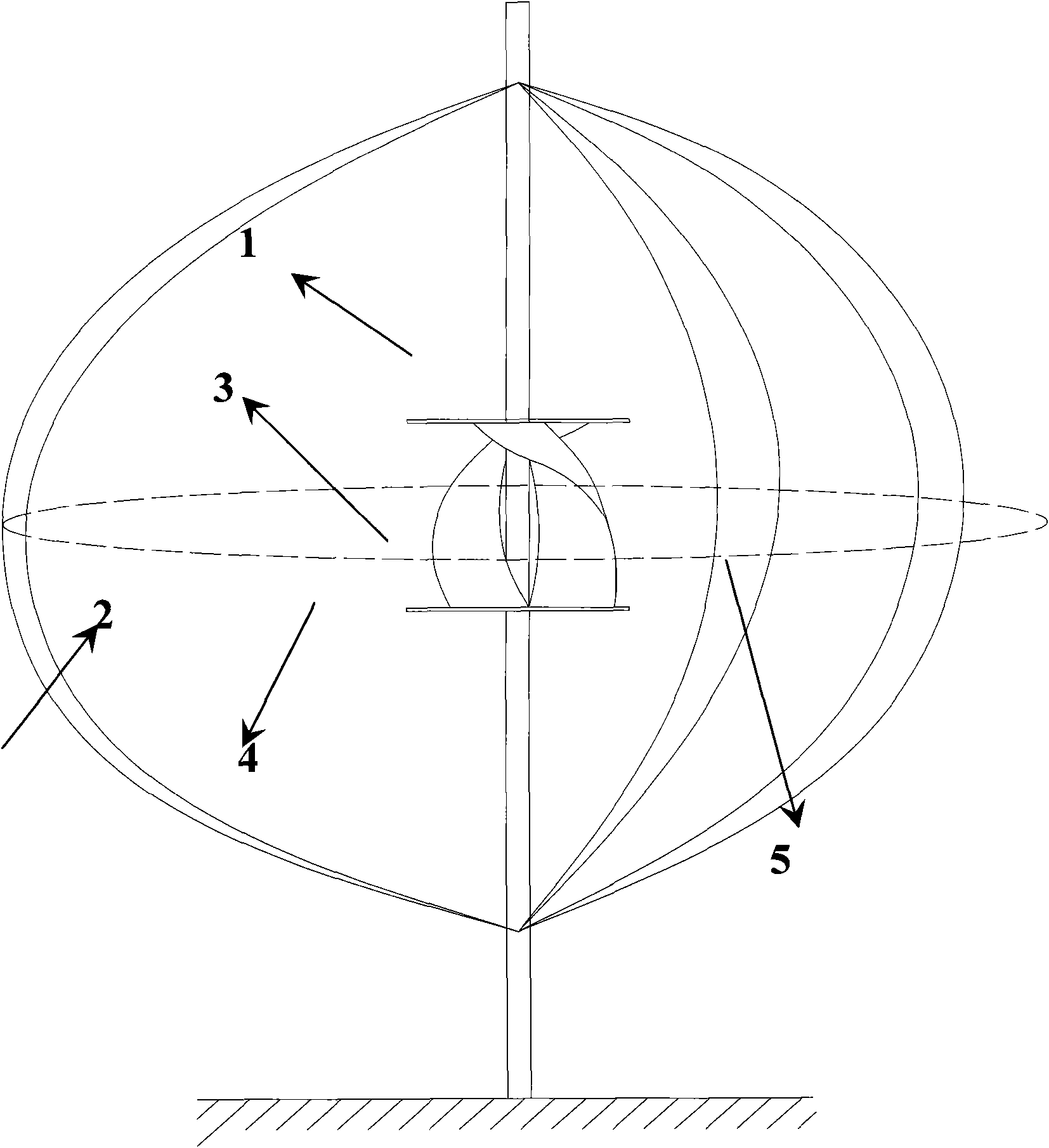
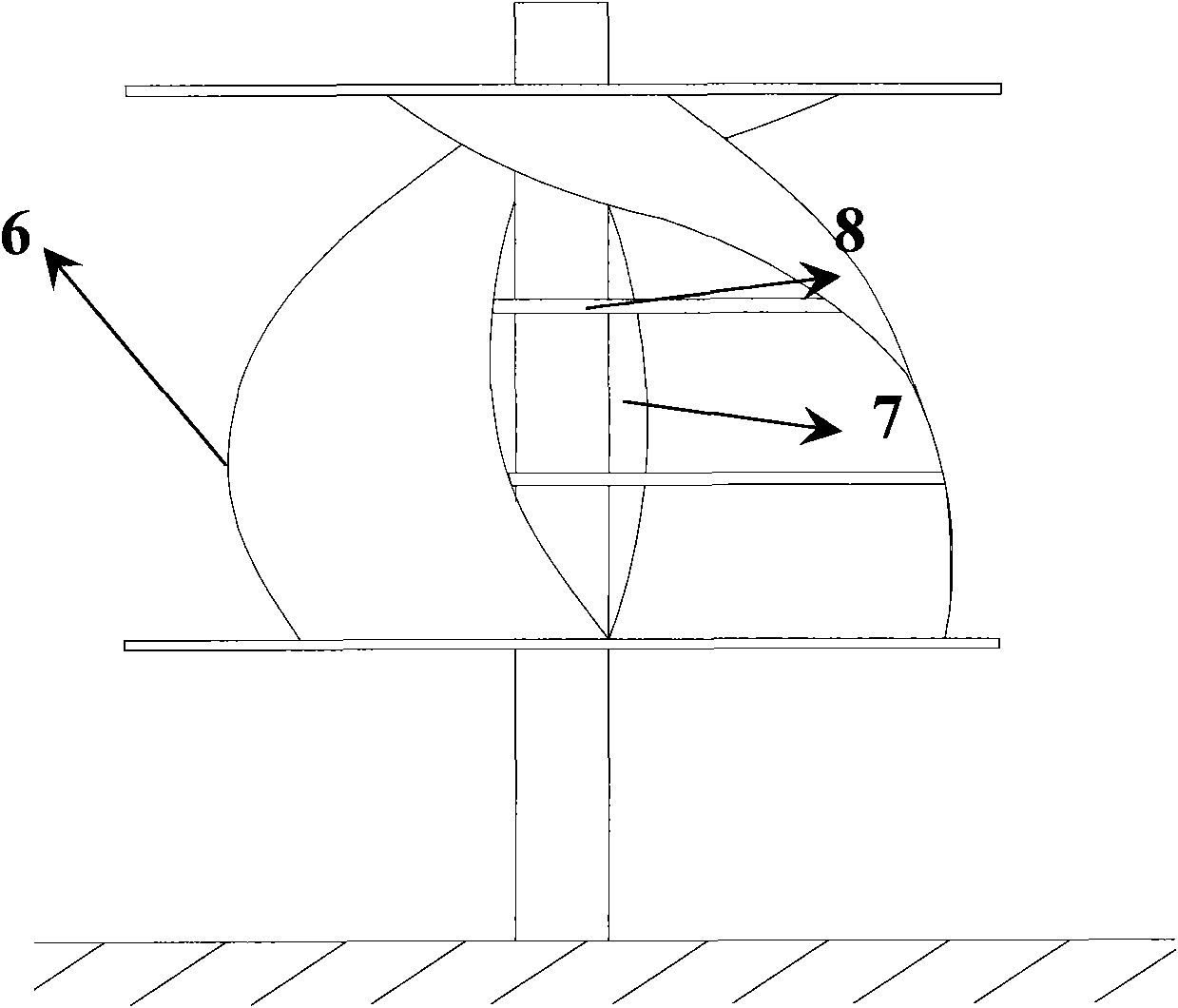
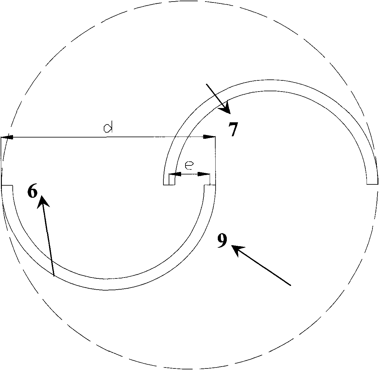
[0017] 1, below in conjunction with accompanying drawing, the present invention is described in detail, as figure 1 As shown, the lift-drag complementary wind rotor of the present invention includes a wind rotor shaft on which 2-3 lift-type blades 2 and 2-3 helical resistance-type blades 3 are installed. figure 2 It is a schematic diagram of the structure of a spiral resistance type blade with an end cover 4 and a partition plate of 2 blades. It is composed of a convex blade 6 and a concave blade 7, separated by 180° in the axial direction, and the cross-section is S-shaped, such as image 3 shown. The spiral resistance blade is formed by rotating the S-shaped blade at a certain angle along the shaft 1 of the wind rotor, and the blade rotation angle is 90° to 360°; the ratio of eccentricity e to blade diameter d (eccentricity coefficient) is between 0 and 0.4 ; The two ends of the blade are provided with a cover 4, and the ratio of its diameter to the rotation diameter 9 is ...


PUM

PropertyMeasurementUnit
Helix angleaaaaaaaaaa
Densityaaaaaaaaaa

Abstract

The invention discloses a lift-drag complementary vertical axis wind wheel, which comprises a wind wheel axis. The wind wheel axis is provided with two to three lift-type blades and two to three drag-type spiral blades, and the ratio of the rotation diameter of the drag-type spiral blades to the rotation equatorial diameter of the lift-type blades is 1:3-7. Compared with the prior art, a structure of which the ratio of the rotation diameter of the drag-type spiral blades to the rotation equatorial diameter of the lift-type blades of 1:3-7 is designed, so that the wind energy utilization ratio of the wind wheel is 5 percent higher than the prior complementary wind wheel. The compactness of the lift-type blades sigma is between 0.13 and 0.4, and the output power of the lift-type blades in the interval is maximum; and a spiral angle of the drag-type blades is designed between 90 and 360 degrees. Partial downwind concave blades are stressed by the thrust of wind at arbitrary intersection angle so as to increase the positive moment of the wind wheel and increase the efficiency of the wind wheel. End covers are arranged at two ends of the drag-type blades and partition boards are arranged in the blades so as to increase the wind gathering capability of concave blades, increase the positive moment and improve the wind wheel efficiency.

Description

technical field [0001] The invention relates to the technology and equipment of lift type and drag type vertical axis wind rotors. Background technique [0002] Wind energy and solar energy are the new energy sources that are receiving great attention at home and abroad, and they are also the new energy sources that will be developed in the 21st century. At present, 90% of the wind turbines in the world use horizontal-axis wind rotors. The design of horizontal-axis wind rotor blades is complicated, and its core design technology is only in the hands of a few suppliers, so the equipment cost is relatively high. In addition, the horizontal axis wind rotor also has the advantages of small starting torque, limited wind direction, high noise of the wind rotor, high installation and maintenance costs, poor reliability of the wind rotor, and relatively low allowable operating wind speed range (5-25m / s). Narrow, long blades, inconvenient transportation and other shortcomings. [0...

Claims


Application Information

Patent Timeline
IPC IPC(8): F03D3/06
CPCY02E10/74
Inventor 赵振宙郑源胡国祥吴玉萍周大庆王涛
Owner HOHAI UNIV
Learn More