
Thin oil lubrication sealing device for vacuum roller liner bearing

A thin oil lubrication and sealing device technology, which is applied in the direction of engine sealing, engine components, mechanical equipment, etc., can solve the problems of shortened life, increased transmission power loss, and loss of paper mill users, so as to prolong the service life and bearing life increased effect

Inactive Publication Date: 2009-10-28
JIANGSU HUADONG PAPER MACHINERY
View PDF0 Cites 9 Cited by
  • Summary
  • Abstract
  • Description
  • Claims
  • Application Information

AI Technical Summary

Problems solved by technology

Due to the long copper pipe, fresh grease has to go through a long pipe to enter the bearing. What's worse, sometimes because the grease stays in the pipe for too long and hardens, the pipe is blocked and the grease cannot pass through.
Later, the oil filling port was changed to the shaft head on the transmission side, which solved the problem of too long grease passage in the past, but because the shaft head on the transmission side rotates when it is working, oil can only be added after the vacuum roller stops, so online oiling cannot be realized. lubricating
[0005] 2. Can not perform rapid heat dissipation
When the speed of the vacuum roller increases, the heat generated by the bearing will increase greatly. Due to the immobility of the grease, the bearing can only dissipate heat through the shaft head on the transmission side. However, the shaft head is thick and the heat transfer path is too long, which often causes poor heat dissipation and causes Bearing sintering, spalling, shortened life and increased transmission power loss
[0006] 3. Due to the simple sealing of grease lubricated bearings, the bearings sometimes enter water and paper fillers during use, causing the bearings to fail immediately
Sometimes the service life is less than three or four days, which greatly affects the operation of the paper machine and brings great losses to the paper mill users

Method used


Image

  • Thin oil lubrication sealing device for vacuum roller liner bearing
  • Thin oil lubrication sealing device for vacuum roller liner bearing
  • Thin oil lubrication sealing device for vacuum roller liner bearing

Examples


Embodiment

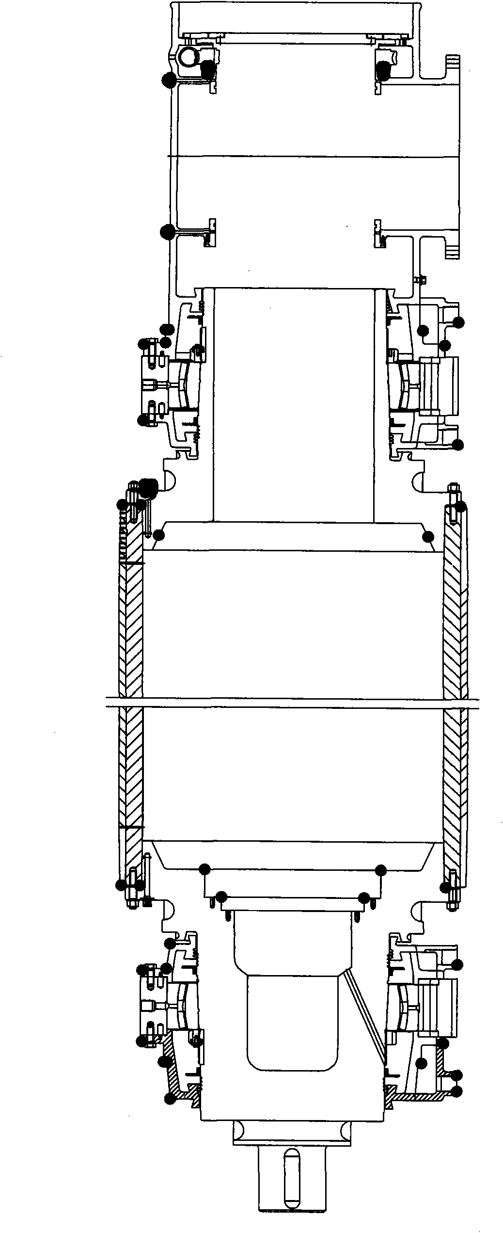
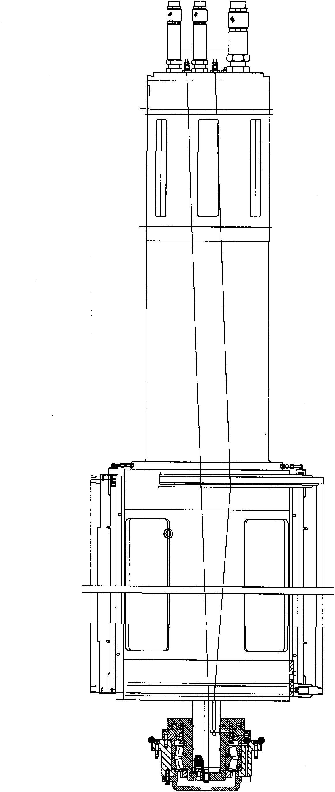
[0026] Embodiment: A vacuum roller liner bearing thin oil lubrication and sealing device, the bearing is set between the inner liner and the shaft head of the transmission side, the bearing seat 1 is fixed on the shaft head of the transmission side, and the bearing 10 is fixedly sleeved on the shaft sleeve 3 Above, the shaft sleeve 3 is fastened to the inner tank shaft 4 through the lock nut 8, the bearing 10 is arranged in the bearing seat 1, the bearing cover 5 is fixed on one end surface of the bearing seat 1, and the bearing cover 5 can just close the inner tank shaft 4 At one end, one end surface of the inner bearing cover 6 is fixed to the other end surface of the bearing housing 1 .

[0027] There is a gap 13 and a flaring chamber 14 between the shaft sleeve 3 and the inner bearing cover 6. The gap 13 communicates with the flaring chamber 14. The flaring chamber 14 is farther away from the bearing 10 than the gap 13, so that the thin oil coming out of the gap 13 can be e...


PUM


Abstract

The invention discloses a thin oil lubrication sealing device for a vacuum roller liner bearing. The bearing is arranged between a liner and a transmission-side shaft head, and a bearing seat is fixed on the transmission-side shaft head; the bearing is fixedly sleeved on a shaft sleeve which is tightly fixed to a liner shaft and tightly fixed by locking nuts; the bearing is arranged in the bearing seat, a bearing cover is fixed on one end surface of the bearing seat and can close one end of a liner shaft; and one end surface of the inner bearing cover is fixed on the other end surface of the bearing seat. The invention realizes the thin oil lubrication sealing of the bearing by mechanical seal in a flaring chamber, oil seal, labyrinth seal and grease seal, is easy to add oil, hardly leaks thin oil, is suitable for the vacuum roller bearing of a papermaking machine at medium and high speeds and prolongs the service life of the bearing.

Description

technical field [0001] The invention relates to a vacuum roller liner bearing lubricating device. Background technique [0002] Suction rolls are commonly used components on paper machines. The vacuum roller is generally composed of an inner tank and an outer shell, the inner tank is fixed, and the outer shell rotates. Usually, one end of the transmission side of the liner is fixed on the rotating shaft head, so a bearing must be connected between the liner and the shaft head. [0003] For a long time, the liner bearing has been lubricated with grease because of its special positional relationship. Grease lubrication has three main drawbacks: [0004] 1. Difficulty refueling. Initially a copper tube was run from the operator side through which the small bearings were greased. Because the copper tube is long, fresh grease has to pass through a long pipeline to enter the bearing. What's worse, sometimes the grease stays in the pipeline for too long and hardens, blocking t...

Claims


Application Information

Patent Timeline
IPC IPC(8): F16J15/16F16J15/447
Inventor 孙春山孙友根刘庚
Owner JIANGSU HUADONG PAPER MACHINERY
Learn More