Check patentability & draft patents in minutes with Patsnap Eureka AI!

Backlight module

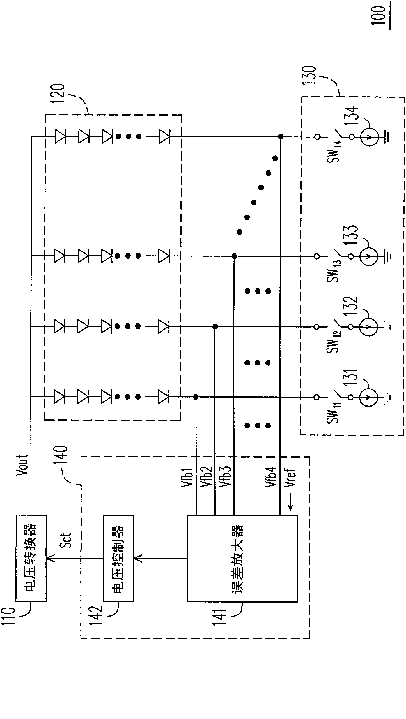
A backlight module and light source array technology, applied in the field of backlight modules, can solve the problems of increasing the number of switches and current sources in the current adjustment circuit 130, reducing the service life, etc.

Inactive Publication Date: 2009-10-28
CHUNGHWA PICTURE TUBES LTD
View PDF0 Cites 6 Cited by
  • Summary
  • Abstract
  • Description
  • Claims
  • Application Information

AI Technical Summary

Problems solved by technology

[0005] However, in the actual application of the existing backlight module 100, since the current of each group of LED strings must be controlled through a switch and a current source, when the contrast of the display image is improved under the area control, the current With the backlight module 100, the number of switches and current sources in the current adjustment circuit 130 must be correspondingly increased
At this time, the existing backlight module 100 will not only consume huge power consumption, but also increase the temperature of its internal circuit, thereby reducing its service life

Method used


Image

  • Backlight module
  • Backlight module
  • Backlight module

Examples


Embodiment Construction

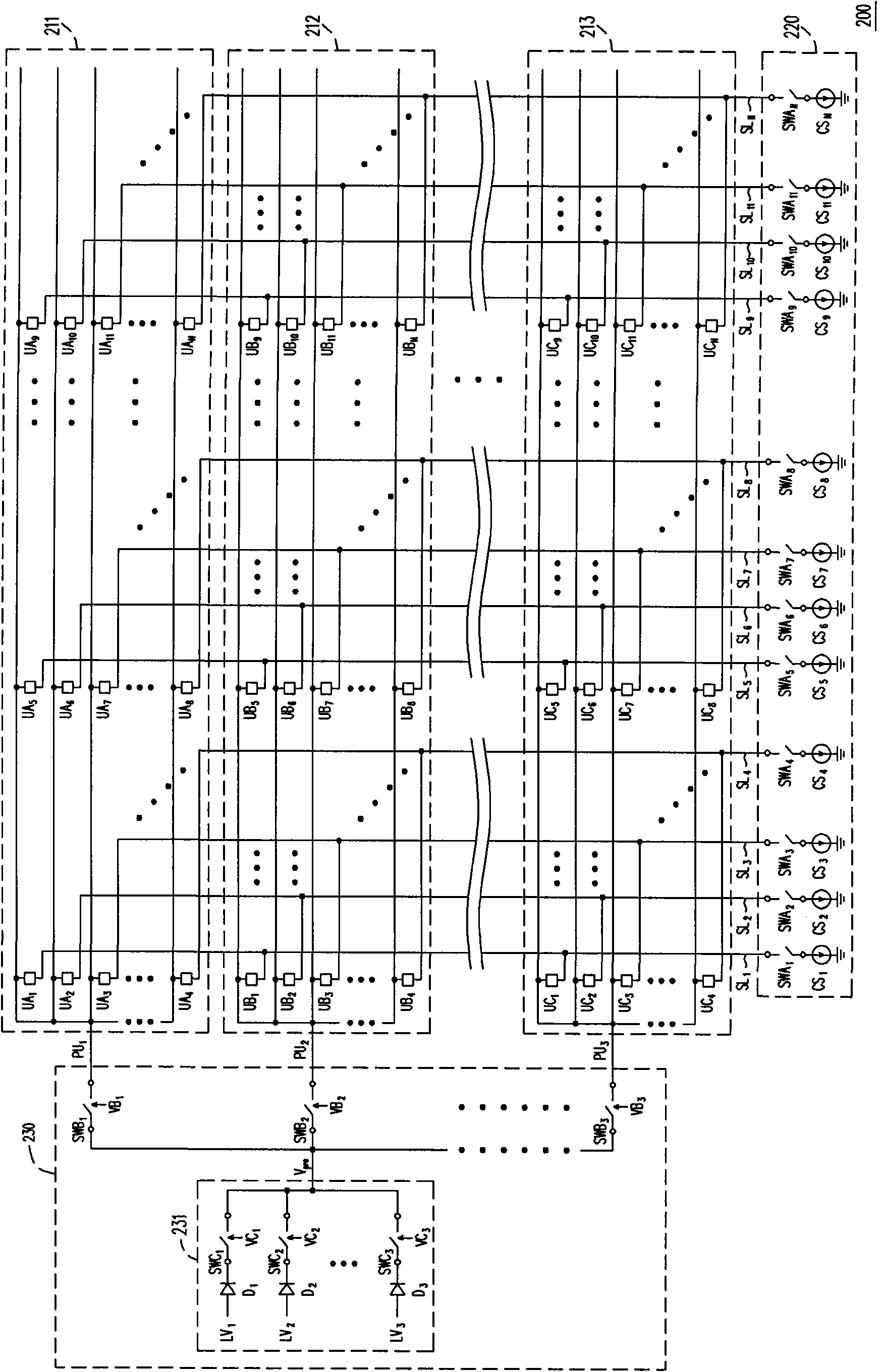
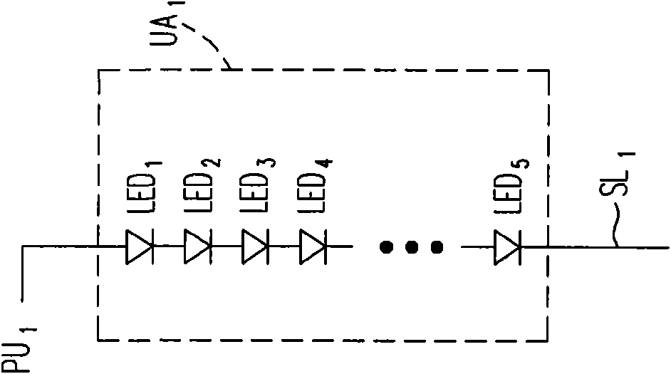
[0057] figure 2 Shown is a circuit block diagram of a backlight module according to an embodiment of the present invention. refer to figure 2 , the backlight module 200 includes a plurality of light source arrays 211 - 213 , a current adjustment circuit 220 and a light source driving circuit 230 . Wherein, each of the light source arrays 211 - 213 includes N light emitting units, where N is an integer greater than 1. For example, the light source array 211 includes N light emitting units UA 1 ~UA N , the light source array 212 includes N light emitting units UB 1 ~UB N , while the light source array 213 includes N light emitting units UC 1 ~UC N .

[0058] From the perspective of the internal structure of the light source array 211, the light emitting unit UA 1 ~UA N The first ends are electrically connected to each other. In addition, the light emitting unit UA 1 The second end of is electrically connected to the potential switching line SL 1 , Lighting unit UA...


PUM


Abstract

The invention discloses a backlight module comprising a plurality of light-source arrays, a current alignment circuit and a light source driving circuit, wherein each light-source array respectively comprises N luminescence units, N is an integer which is more than 1, the first ends of the luminescence units are electrically connected with each other, and the second end of the ith luminescence unit is electrically connected with the ith potential switching line, wherein i is an integer which is more than or equal to 1 and less than or equal to N; on the other hand, the current alignment circuit can supply and control the current of each light-source array through the ith potential switching line; and the light source driving circuit is used for sequentially starting the light-source arrays.

Description

technical field [0001] The present invention relates to a light source module, and in particular to a backlight module. Background technique [0002] In recent years, backlight modules in liquid crystal displays mostly use light emitting diodes (Light Emitting Diodes, LEDs), which have the characteristics of long life, high efficiency, and low environmental pollution, as backlight sources. Among them, the size of the light source emitted by the light-emitting diode is related to the image quality of the liquid crystal display, so the current industrial technology is all focused on the design of the backlight module. [0003] figure 1 It is shown as a circuit block diagram of an existing backlight module. refer to figure 1 , the existing backlight module 100 utilizes the output voltage V generated by the voltage converter 110 out to drive the LED array 120, wherein the LED array 120 is composed of a plurality of LED strings. The current regulation circuit 130 is used to ...

Claims


Application Information

Patent Timeline
IPC IPC(8): F21V23/00H05B37/02G02F1/13357G02F1/1335
Inventor 赵翰楀邹健龙
Owner CHUNGHWA PICTURE TUBES LTD
Features
  • R&D
  • Intellectual Property
  • Life Sciences
  • Materials
  • Tech Scout
  • Unparalleled Data Quality
  • Higher Quality Content
  • 60% Fewer Hallucinations
Learn More