Check patentability & draft patents in minutes with Patsnap Eureka AI!

Flexible supporting structure for the back of reflecting mirror

A flexible support and support structure technology, applied in installation, optics, instruments, etc., can solve the problems of increased mirror mass, increased mirror weight, and reduced light weight, achieving the effect of simple and reliable operation and avoiding assembly stress

Inactive Publication Date: 2009-10-28
CHANGCHUN INST OF OPTICS FINE MECHANICS & PHYSICS CHINESE ACAD OF SCI
View PDF0 Cites 25 Cited by
  • Summary
  • Abstract
  • Description
  • Claims
  • Application Information

AI Technical Summary

Problems solved by technology

If the multi-point back support method adopted for the back support of large-diameter mirrors is applied to small and medium-diameter mirrors, the size of the structural parts of the back support will be reduced due to the small back area of ​​the mirror, which will cause difficulty in processing thus multiplying
In addition, multi-point back support requires a large area to implement. For small and medium-caliber reflectors, its occupation ratio is relatively large, which greatly reduces the degree of light weight and increases the quality of the reflector.
If the mirror is fixed in the form of a traditional outer frame, the size and thickness of the outer frame required will inevitably increase correspondingly due to the relatively large size of the mirror, which will also greatly increase the weight of the mirror

Method used


Image

  • Flexible supporting structure for the back of reflecting mirror
  • Flexible supporting structure for the back of reflecting mirror
  • Flexible supporting structure for the back of reflecting mirror

Examples


Embodiment Construction

[0017] The present invention is described in further detail below in conjunction with accompanying drawing:

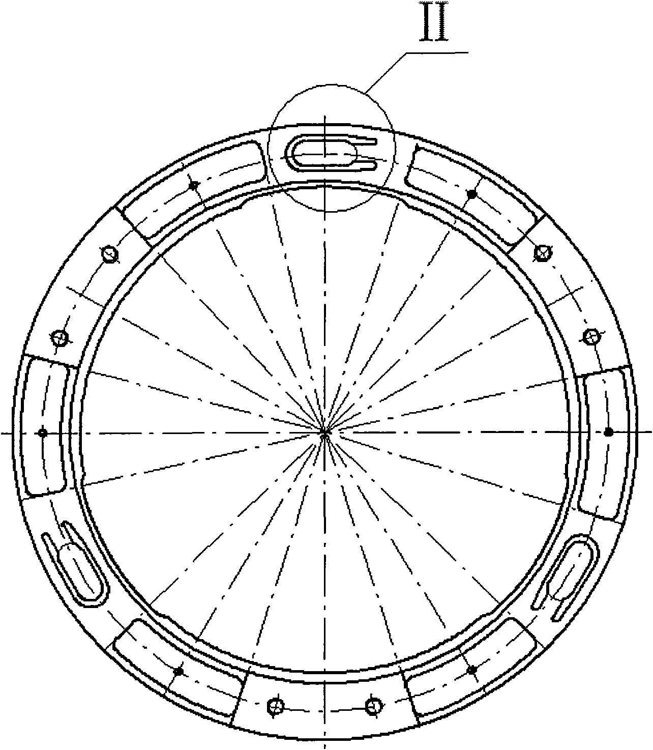
[0018] Such as Figure 1 to Figure 8 As shown, a kind of reflector back flexible support structure of the present invention comprises an upper ring 1, a lower ring 2, a first flexible part 3, a second flexible part 4 and a third flexible part 5, and the upper ring 1 and the lower ring 2 are The metal rings parallel to each other are connected by three flexible parts forming an angle of 120°. The lower ring 2 is bonded to the back of the mirror, and the upper ring 1 is fixed on the corresponding position of the camera body through the back plate.

[0019] The horizontal projection of the first flexible piece 3 is shown in view II, and the sectional projection is shown in view III. The structures of the horizontal projections and sectional projections of the other two flexible pieces are the same as those of the first flexible piece 3 . The projections of the first flex...


PUM


Abstract

The invention discloses a flexible supporting structure for the back of a reflecting mirror, relating to the technical field of precision machinery for optical systems; the supporting structure comprises an upper ring (1), a lower ring (2), a first flexible element (3), a second flexible element (4) and a third flexible element (5); the upper ring (1) is fixed on the body of a camera, the lower ring is adhered to the back of the reflecting mirror, and the first flexible element (3), the second flexible element (4) and the third flexible element (5) are all positioned between the upper ring (1) and the lower ring (2) and connect the upper ring (1) with the lower ring (2). During the assembly of components of the reflecting mirror, the flexible supporting structure leads the operation simple and reliable and avoids assembling stress caused by conducting a plurality of operations to the reflecting mirror.

Description

technical field [0001] The invention belongs to the technical field of optical system precision machinery, can be applied to the back support of a reflector with an aperture below 300mm in a space remote sensing camera or a ground-based telescopic system, and relates to a flexible support structure for the back of the reflector. Background technique [0002] With the application of off-axis astigmatism optical systems in space cameras, large and medium aperture mirrors usually use multi-point back support. With the rapid development of off-axis astigmatism optical systems in space applications, small and medium aperture mirrors Back support also needs to find a solution. If the multi-point back support method adopted for the back support of large-diameter mirrors is applied to small and medium-diameter mirrors, the size of the structural parts of the back support will be reduced due to the small back area of ​​the mirror, which will cause difficulty in processing thus multi...

Claims


Application Information

Patent Timeline
IPC IPC(8): G02B7/182G02B7/192
Inventor 翟岩王忠素
Owner CHANGCHUN INST OF OPTICS FINE MECHANICS & PHYSICS CHINESE ACAD OF SCI
Features
  • R&D
  • Intellectual Property
  • Life Sciences
  • Materials
  • Tech Scout
  • Unparalleled Data Quality
  • Higher Quality Content
  • 60% Fewer Hallucinations
Learn More