Vehicle control device
A technology for control devices and vehicles, which is applied to vehicle components, automatic starting devices, transmission control, etc., and can solve problems such as driver distrust and reaching the locked state
- Summary
- Abstract
- Description
- Claims
- Application Information
AI Technical Summary
Problems solved by technology
Method used
Image
Examples
Embodiment approach 1
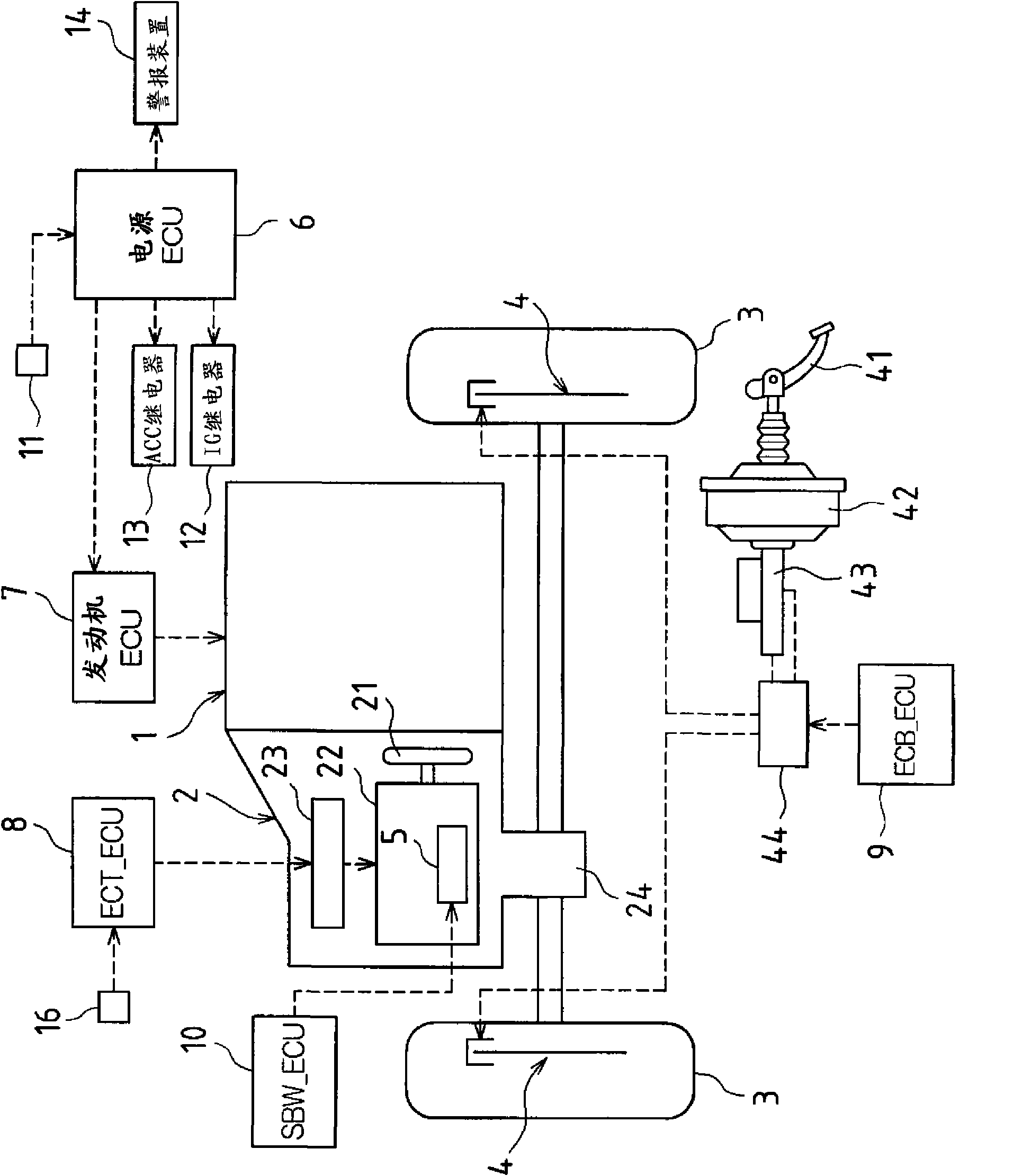
[0058] Figure 1 to Figure 6 Embodiment 1 of this invention is shown. Before the description of the characteristic part of the present invention, refer to figure 1 , an outline of a power train of a vehicle to which the present invention is applied will be described.
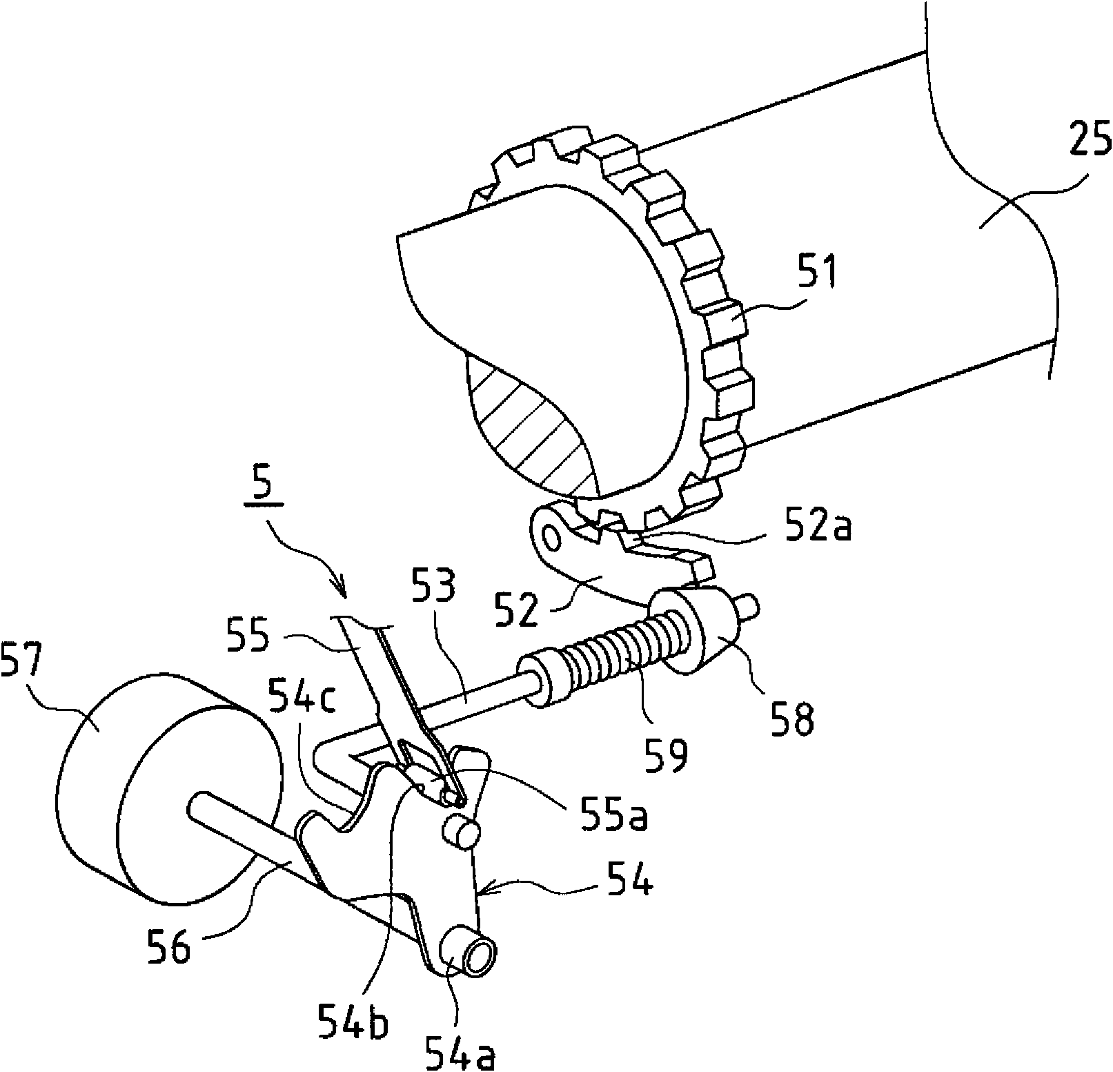
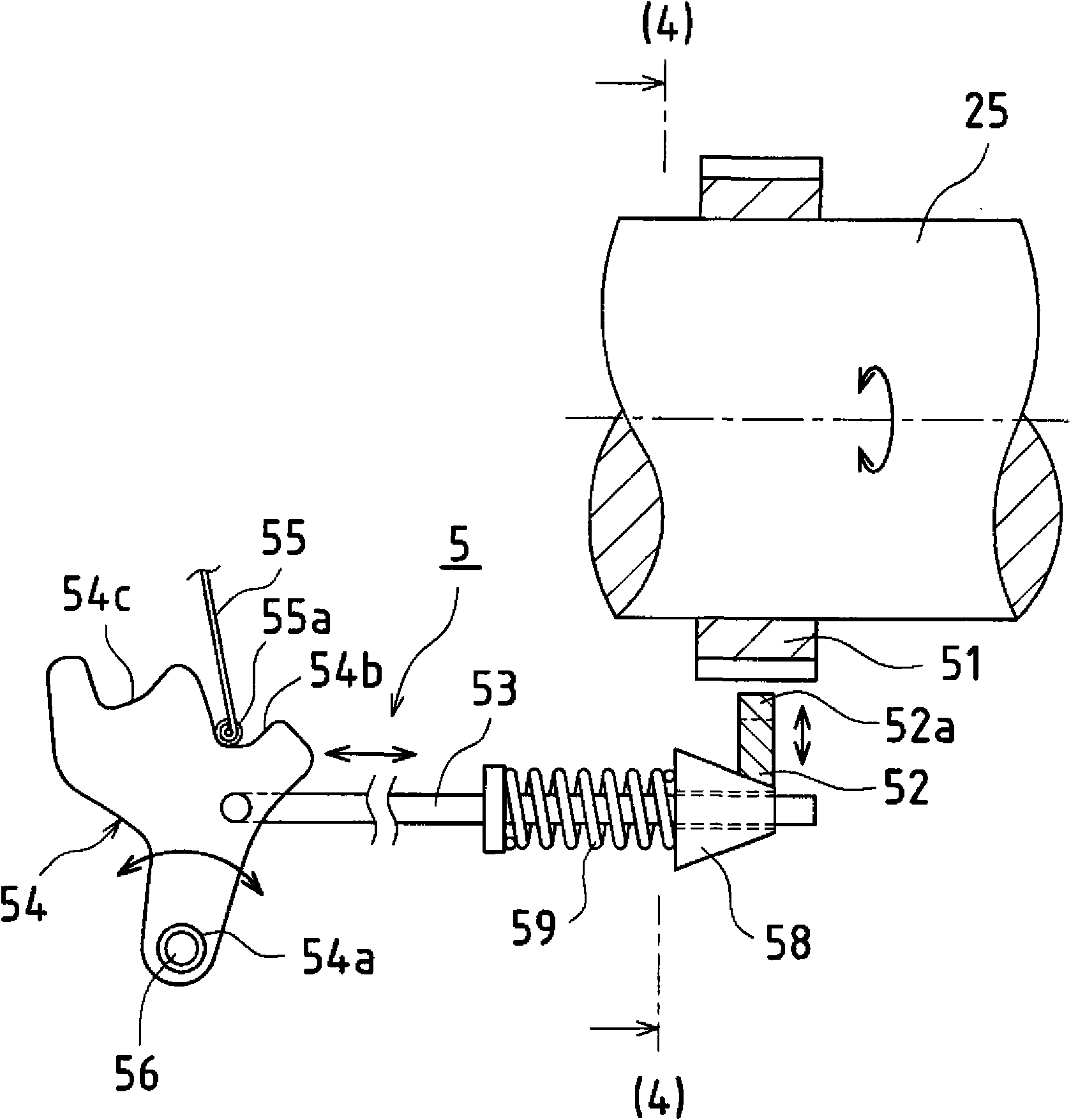
[0059] figure 1 In , it represents a front-engine / front-wheel-drive (FF) powertrain. In the figure, 1 is an engine as a driving source, 2 is an automatic transmission, 3 is a driving wheel, 4 is a foot brake type brake, 5 is a parking mechanism, 6 is a power supply ECU (Electronic Control Unit), and 7 is an engine ECU. , 8 is ECT(Elctronic Controlled Automatic Transmission)_ECU, 9 is ECB(Elctronic Controlled Brake system)_ECU, 10 is SBW(Shift by Wire)_ECU.
[0060] Since these basic configurations are the same as generally known configurations, the parts not directly related to the present invention will be briefly described.
[0061] The engine 1 is a gasoline engine or a diesel engine, and its operation i...
Embodiment approach 2
[0132] Regarding Embodiment 2 of the vehicle control device according to the present invention, for example, refer to Figure 7 Describe in detail. Figure 7 It is a flow chart used in describing the operation of automatic parking control by SBW_ECU.
[0133] This second embodiment is based on the premise of the configuration of the above-mentioned first embodiment, and is characterized by omitting Image 6 Step S29 (representing the notification operation of the operation execution request of the brake 4).
[0134] In short, when the parking mechanism 5 is actuated by the automatic parking control, if the vehicle speed increases due to, for example, parking on a hill and the vehicle deviates, the notification is only made by extending the reference time as in Embodiment 1 above.
[0135] Furthermore, the operation of the automatic parking control by the power supply ECU 6 is the same as that of the first embodiment described above.
[0136] In the case of this second embod...
Embodiment approach 3
[0139] Regarding Embodiment 3 of the vehicle control device according to the present invention, for example, refer to Figure 8 Describe in detail. Figure 8 It is a flow chart used in describing the operation of automatic parking control by SBW_ECU.
[0140] This third embodiment is based on the premise of the configuration of the above-mentioned second embodiment, and is characterized in that in Figure 7 Steps S40 and S41 are added after step S28.
[0141] That is to say, in the third embodiment, in general, when the parking mechanism 5 is actuated by the automatic parking control, after the vehicle speed increases, the reference time is extended and the notification is made as in the second embodiment described above. The case is handled as follows, that is, it is automatically performed: the process of blocking the transmission of driving force from the automatic transmission 2 to the drive wheels 3 ( Figure 8 step S40), and the process of actuating the brake 4 to app...
PUM
 Abstract
Description
Claims
Application Information
 - R&D
- Intellectual Property
- Life Sciences
- Materials
- Tech Scout
- Unparalleled Data Quality
- Higher Quality Content
- 60% Fewer Hallucinations
Browse by: Latest US Patents, China's latest patents, Technical Efficacy Thesaurus, Application Domain, Technology Topic, Popular Technical Reports.
© 2025 PatSnap. All rights reserved.Legal|Privacy policy|Modern Slavery Act Transparency Statement|Sitemap|About US| Contact US: help@patsnap.com


