
Wood floor carbonization processing method

A processing method and wood flooring technology, applied in wood processing equipment, wood compression, manufacturing tools, etc., can solve the problems of large investment in process equipment, slow cooling speed, long production cycle, etc., to avoid low success rate and avoid floor deformation , The effect of improving the yield

Inactive Publication Date: 2011-12-28
周发荣
View PDF0 Cites 0 Cited by
  • Summary
  • Abstract
  • Description
  • Claims
  • Application Information

AI Technical Summary

Problems solved by technology

Its process equipment investment is large, the production cycle is long (generally takes 2 days), the carbonization process is complicated, the production cost is high, the heat energy consumption is large, the risk is also high, and there are technical difficulties in processing thin floor skins
Moreover, the defects of the floor during the carbonization process are also more serious, such as knots falling off, deformation, cracking, large color difference, etc.
There is also a hot press carbonization method in China, which uses an ordinary hot press to directly heat press and carbonize the floor, but the floor is carbonized in the existing ordinary hot press at a temperature of 160 ° C or above, and the carbonization has not yet been completed. The four sides of the floor have already started to catch fire. At this time, the only way is to use water cooling method to spray the floor to make the temperature of the floor drop below the ignition point.
This carbonization method has a low success rate and a slow cooling rate. The steam generated by the spray is easy to scald the workers. Once it is not properly controlled, it is very likely to cause a fire.
[0004] In addition, after the floor is carbonized by the above methods, the density will decrease, and some mechanical properties will also decrease. For example, the flexural strength, impact toughness and nail holding force of the floor will decrease significantly, which will affect the performance of the floor.

Method used


Image

  • Wood floor carbonization processing method
  • Wood floor carbonization processing method

Examples


Embodiment 1

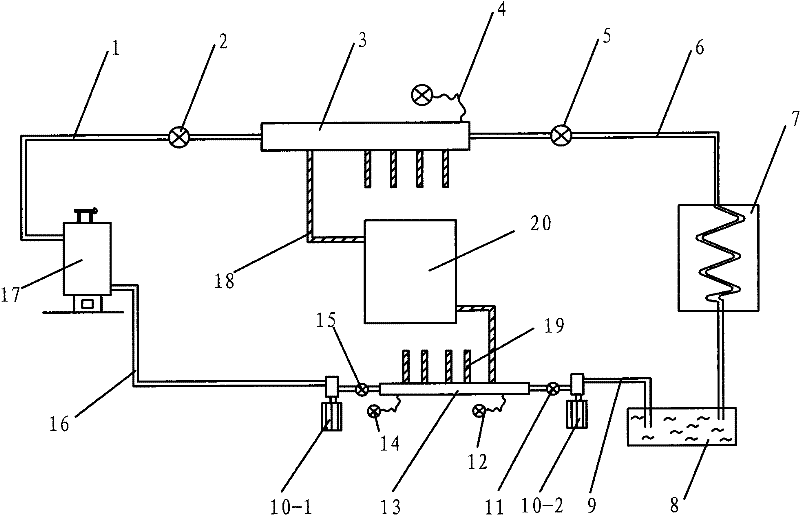
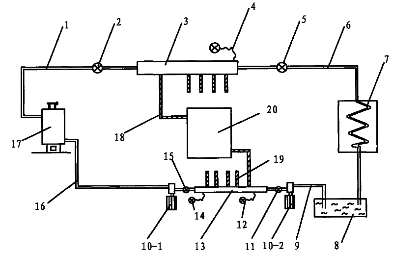
[0032] Embodiment 1: as figure 1 The shown heat press machine comprises: a heat press chamber, an oil guide part connected with the heat press chamber, a hot oil device connected with the oil guide part, the oil guide part is also connected with a cold oil device, and the heat The press chamber includes a hot press plate 20, which is made of steel, with a length of 2500 mm, a width of 2000 mm, and a height of 18.5 mm.

[0033] A sealing strip is respectively installed on the four sides of the hot pressing plate 20, and the sealing strip is made of steel, and two of them installed on the long sides are fixed sealing strips, and the fixed sealing strip is 40 mm wide, 2500 mm long, and 18.5 mm high. mm, the other two are movable sealing strips with a width of 40mm, a length of 1900mm, and a height of 18.5mm. The length of the movable sealing strip is 20mm shorter than the gap between the two fixed sealing strips, so that there is a 10mm gap between the left and right sides of th...


PUM


Abstract

The invention relates to the field of wood floor processing, in particular to a wood floor carbonization processing method. The wood floor carbonization processing method comprises the following steps (1), preliminary treatment: cutting the wood into the shape of the floor to obtain the floor embryo; (2), hot pressing carbonization: putting the floor embryo into a hot press machine for high-temperature carbonization , to obtain the carbonized wood embryo; (3), cooling: place the carbonized wood embryo in the hot press and cool it to below 160°C through the cooling oil device of the hot press; (4), finished product: the cooled carbonized wood embryo from Take it out from the hot press and process it later to get the finished carbonized floor. The method directly completes the steps of hot-pressing carbonization and cooling in the hot-pressing machine, which makes the operation simple and convenient for workers, makes the whole carbonization process safe and controllable, improves the rate of finished products, and further improves the quality of the finished floor.

Description

technical field [0001] The invention relates to the field of wood floor processing, in particular to a wood floor carbonization processing method. Background technique [0002] Since the floor is prone to warping and deformation during use, it is also easy to be corroded and mildewed, so wood products often need to undergo a series of treatments for the raw material floor used in the production. Floor carbonization treatment technology has the characteristics of good dimensional stability, corrosion resistance, excellent weather resistance, and does not contain any chemical ingredients, does not pollute the environment, and has outstanding environmental protection. , landscape and interior decoration industries are widely used. [0003] At present, the carbonization methods of floors and floors used in China are generally tank type and kiln type. In order to prevent the floor from burning during the high-temperature carbonization process, the tank-type and kiln-type floor ...

Claims


Application Information

Patent Timeline
Patent Type & Authority Patents(China)
IPC IPC(8): B27M3/04B27M1/02B27M1/06B27M1/08
Inventor 周发荣
Owner 周发荣
Learn More