Conveyor chain and conveyor chain conveying device
A technology of conveying chain and conveying surface, which is applied in the direction of conveyor, transportation and packaging, escalator, etc., can solve the problems of disengagement of conveying chain, increase or decrease of driving force, change of the width of the conveying device of difficult conveying chain, etc., so as to achieve smooth chain walking, The effect of reducing the transmission loss and realizing the freedom of use
- Summary
- Abstract
- Description
- Claims
- Application Information
AI Technical Summary
Problems solved by technology
Method used
Image

Examples
Embodiment 1
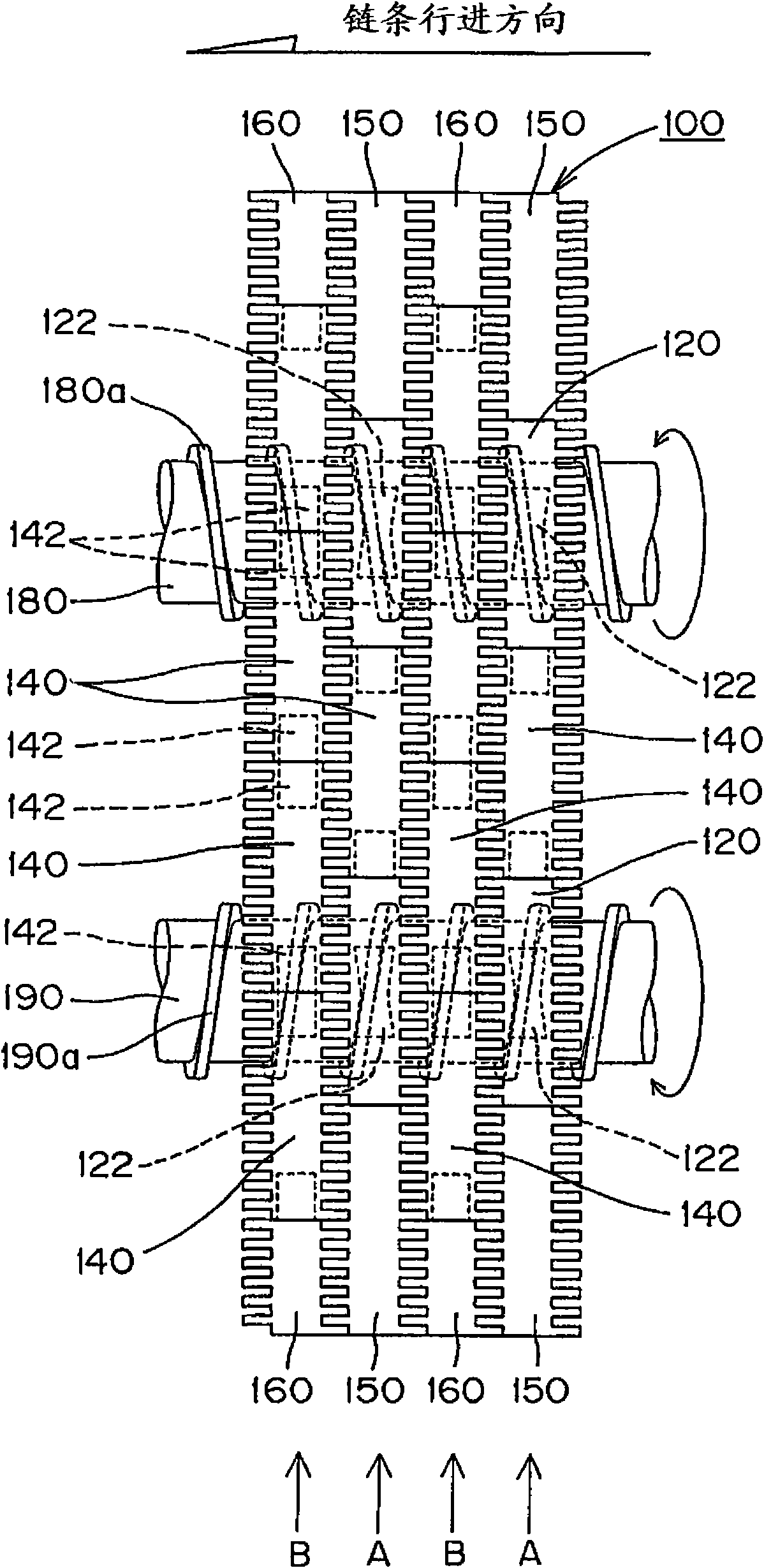
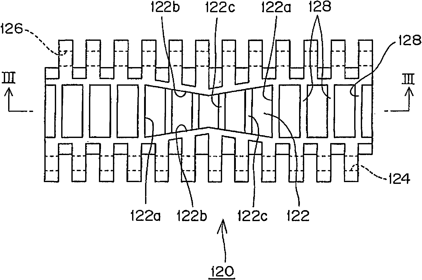
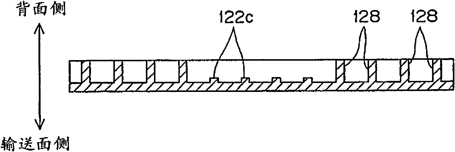
[0036] Here, refer to Figure 1 to Figure 5 Embodiment 1 of the conveyor chain and the conveyor chain conveyor of the present invention will be described. figure 1 It is a top view of the partial appearance of the conveyor chain 100 and the conveyor chain conveying device of the first embodiment viewed from the conveying surface side. figure 2 It is a plan view when the helical drum engaging assembly 120 constituting one of the conveying assemblies of the conveyor chain 100 is viewed from the back, image 3 for along figure 2 The cross-sectional view when the line III-III is cut, Figure 4 It is a plan view when the central assembly 140, one of the conveying assemblies constituting the conveyor chain 100, is viewed from the back, Figure 5 It is a plan view of the full-scale end unit 150, which is one of the conveying units constituting the conveyor chain 100, viewed from the back.
[0037] like figure 1 As shown, the conveyor chain 100 of this embodiment consists of a ...
Embodiment 2
[0048] Below, refer to Figure 6 to Figure 11 Example 2 which is another embodiment of the conveyor chain and the conveyor chain conveying device of the present invention will be described. Image 6 It is a top view of the partial appearance of the conveyor chain 200 and the conveyor chain conveying device of the second embodiment viewed from the conveying surface side. Figure 7 It is a plan view of the screw drum engaging unit 220 constituting one of the conveying units constituting the conveyor chain 200 viewed from the back. Figure 8 It is a plan view of another shape of the spiral drum engaging assembly 270 viewed from the back. Figure 9 for along Figure 7 The cross-sectional view when the IX-IX line is cut. Figure 10 for along Image 6 The cross-sectional view when the X-X line is cut. Figure 11 for Figure 10 Enlarged view of Part IX of . and in Image 6 In , in order to clearly distinguish the boundary of each conveying unit, the rib formed parallel to the...
Embodiment 3
[0056] Below, refer to Figure 12 Example 3, which is another embodiment of the conveyor chain and the conveyor chain conveying device of the present invention, will be described. Figure 12 It is a top view of the partial appearance of the conveyor chain 300 and the conveyor chain conveying device in Embodiment 3 viewed from the conveying surface side. and in Figure 12 In , in order to clearly distinguish the boundary of each conveying unit, the ribs formed parallel to the chain running direction on the back side of each conveying unit are omitted, and only the running inducing concave portion 322 is shown with a dotted line.
[0057] Compared with the conveyor chain and the conveyor chain conveyor of Embodiment 1 of the present invention, the conveyor chain and the conveyor chain conveying device according to Embodiment 3 of the present invention, except that the width of the conveyor chain and the number of helical drums are 2 times, the basic The device configuration an...
PUM
 Abstract
Description
Claims
Application Information
 - R&D Engineer
- R&D Manager
- IP Professional
- Industry Leading Data Capabilities
- Powerful AI technology
- Patent DNA Extraction
Browse by: Latest US Patents, China's latest patents, Technical Efficacy Thesaurus, Application Domain, Technology Topic.
© 2024 PatSnap. All rights reserved.Legal|Privacy policy|Modern Slavery Act Transparency Statement|Sitemap