
Vehicle transportation device applied to solid garage

A technology for conveying devices and vehicles, which is applied to buildings, building types, buildings, etc. where cars are parked, and can solve problems such as poor commonality of parts, low modularity, and unstable equipment operation.

Active Publication Date: 2009-11-04
北京大兆新元停车设备有限公司
View PDF0 Cites 5 Cited by
  • Summary
  • Abstract
  • Description
  • Claims
  • Application Information

AI Technical Summary

Problems solved by technology

When the equipment adopting this way of transmitting force is running, the transmission noise is large; when the equipment stops at the same time as the driving parts, the transmission parts of the equipment are easy to wear and be damaged, and the operation of the whole equipment is not stable.
Moreover, the degree of modularization of the equipment is very low, and the versatility of the equipment and its parts is very poor.

Method used


Image

  • Vehicle transportation device applied to solid garage
  • Vehicle transportation device applied to solid garage
  • Vehicle transportation device applied to solid garage

Examples


Embodiment 1

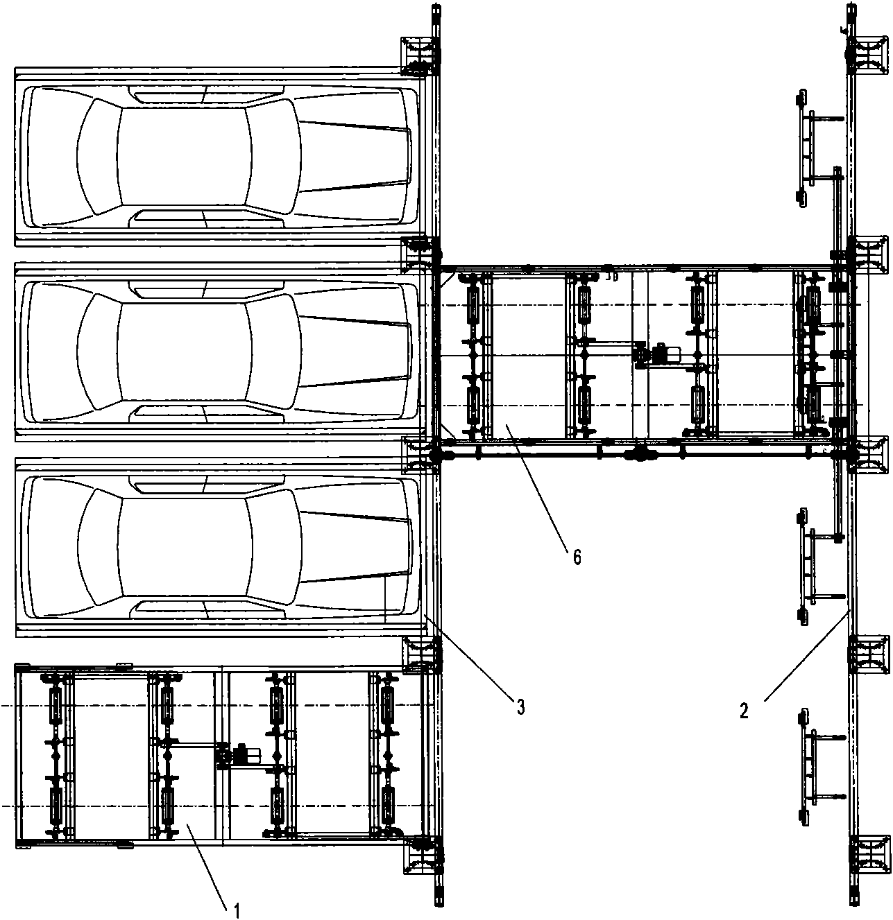
[0025] figure 1 It is a schematic diagram of a vehicle conveying device in the present invention, which is suitable for a parking lot with a row of parking spaces on both sides of the middle passage. The equipment is composed of a plurality of longitudinal parking units 1 arranged together, a transverse conveying track 2, a vehicle loading plate 3 and a transport unit 6 installed on the transverse conveying track for transversely transporting vehicles. Each longitudinal parking unit 1 is an independent structural module, which can be used alone or in combination as required. The conveying mechanism in the transport unit 6 is the same as that in the longitudinal parking unit 1 .

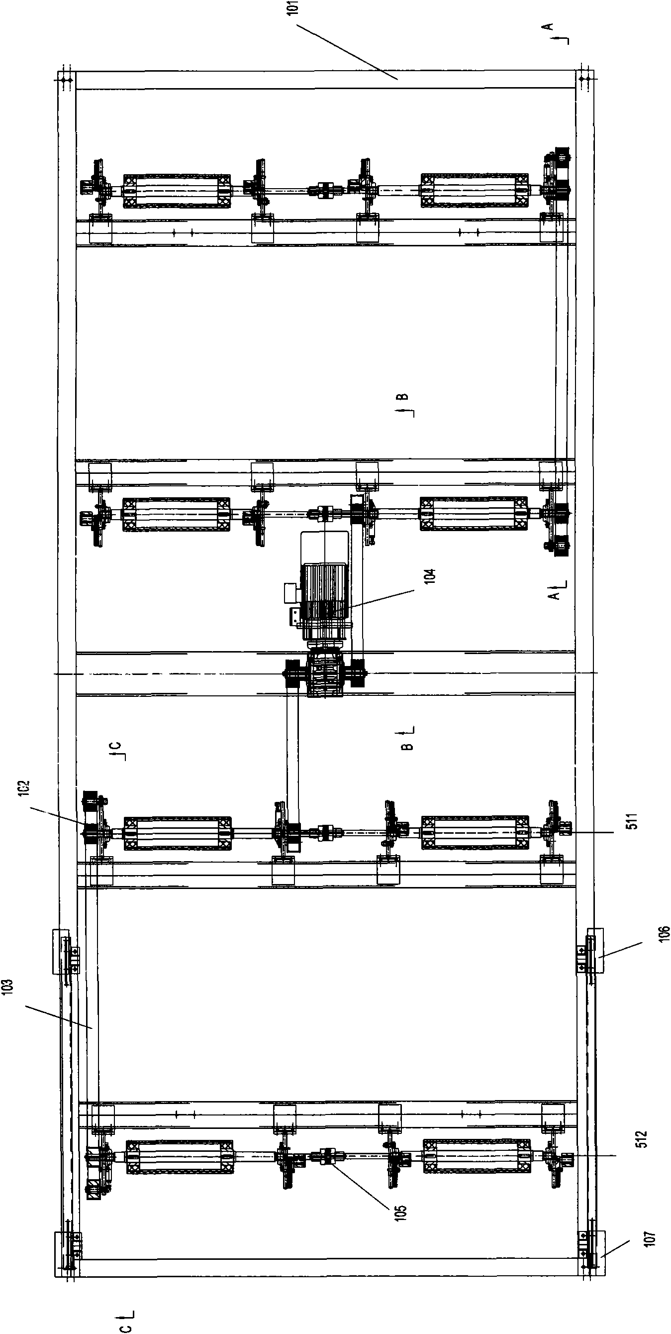
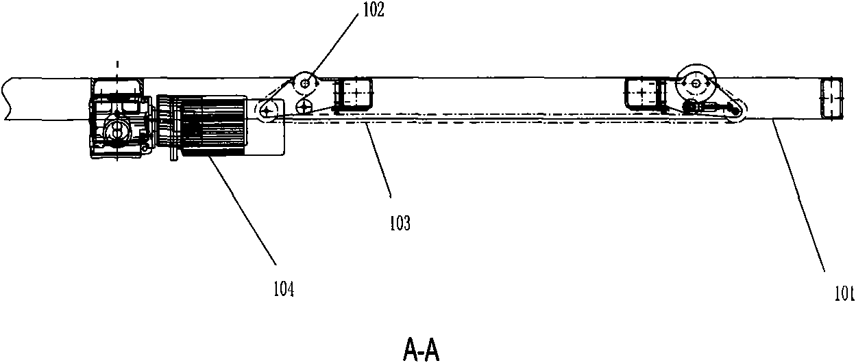
[0026] Wherein the vertical parking unit 1, such as Figure 2a , 2b , 2c and 2d show: including: fixed frame 101, rollers, pulley 102, toothed belt 103, longitudinal driving device 104, deceleration sensor 106 and stop sensor 107. The fixed frame 101 is welded by rectangular tubes. The transmissi...

Embodiment 2

[0028] image 3 It is a structural schematic diagram of another vehicle conveying device of the present invention: this kind of vehicle conveying device is suitable for use in a parking lot with multiple rows of parking spaces on both sides of the middle passage. This kind of vehicle conveying device is made up of a plurality of vertically and horizontally two-way parking units 4 that are arranged together in every row, and the transport unit 6 that is installed on the transverse conveying track 2 and is used for transversely transporting the vehicle on the transverse conveying track 2, the vehicle-loading plate 3, each Each vertical and horizontal two-way parking unit 4 is an independent structural module, which can be used alone or in combination as required. The conveying mechanism in the transport unit 6 is the same as that in the longitudinal parking unit 1 .

[0029] Such as Figure 4a , 4b As shown in . The longitudinal moving unit is composed of rollers, pulleys 40...


PUM


Abstract

A vehicle transportation device comprises a parking unit, a cross feed mechanism and a car carrying board, wherein the driving mechanism of the parking unit is a jugged driving mechanism with a roller and is composed of a driving roller, a belt pulley, a cog belt and a driving mechanism; the driving mechanism transmits power to the driving roller by a driving belt pulley, a driven belt pulley and the cog belt, and the car bearing board is transported and controlled by friction force of the roller. The vehicle transportation device disclosed in the invention adopts belt pulley cog belt drive which runs steadily and quietly with accurate transmission. Besides, each parking unit is independently arranged, overall modularization is realized is modularized, assembly is flexible and convenient, horizontal movement or multiplayer circulation can be assembled at will according to foundation, applicability is strong, damage on the roller which is in high speed rotation for instant stop caused by fault is eliminated, and the service life of the device can be prolonged.

Description

technical field [0001] The patent invention relates to a vehicle conveying device, especially a vehicle conveying device for a three-dimensional garage. Background technique [0002] With the development of the modern automobile industry and the improvement of people's living standards, the number of automobiles in cities is increasing year by year. The parking of cars has just become a difficult problem in traffic management and municipal construction. The vehicle parking lot is developing in a multi-layer and three-dimensional direction. What follows is exactly how to build a safe and reliable parking lot for transporting vehicles with a simple structure. The vehicle parking equipment used in the current three-dimensional parking lot is generally used to transmit power in two ways: sprocket chain and roller wire rope, and most of the connections between the transmission parts are fixed by keys, pins or direct welding. way of transmitting force. When the equipment using...

Claims


Application Information

Patent Timeline
Patent Type & Authority Applications(China)
IPC IPC(8): E04H6/22
Inventor 杨晓川李国胡建强张利伟韦玉香张国旗
Owner 北京大兆新元停车设备有限公司
Learn More