
Power controller with adaptation power supply

A power control device and self-adaptive technology, which can be applied in the direction of conversion equipment without intermediate conversion to AC, can solve the problems of wasting power and increasing the power consumption of communication equipment, and achieve the purpose of reducing power consumption, improving self-adaptive ability, and strong compatibility. Effect

Inactive Publication Date: 2009-11-04
宋华华
View PDF0 Cites 5 Cited by
  • Summary
  • Abstract
  • Description
  • Claims
  • Application Information

AI Technical Summary

Problems solved by technology

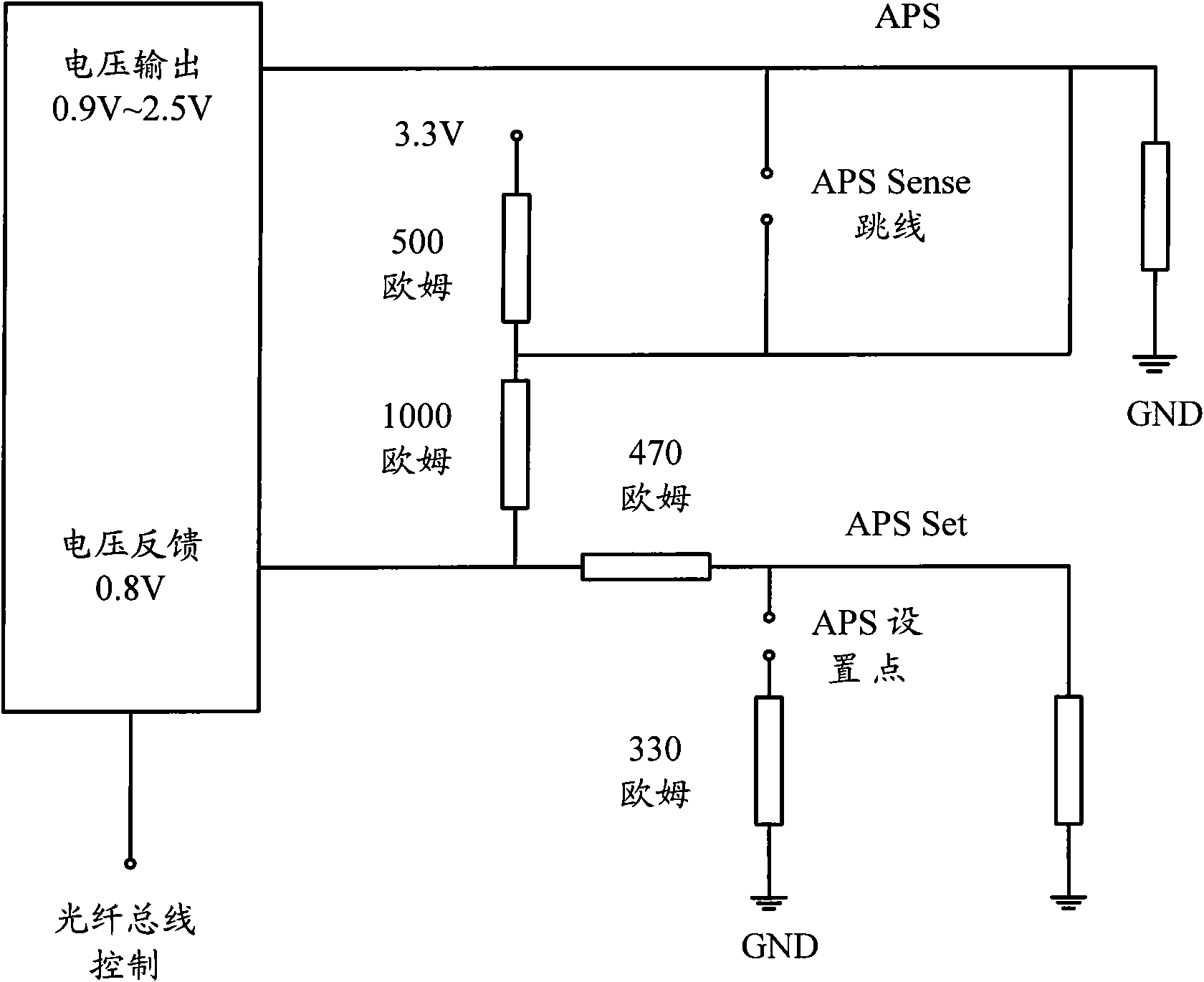
from figure 1 The connection relationship between the APS and the optical transceiver module board in the figure shows that no matter whether the optical transceiver module board is in place, the APS still supplies power to the relevant circuits of the optical transceiver module. Since there are many optical transceiver modules in the same device, this This power supply method will increase the power consumption of communication equipment and waste power

Method used


Image

  • Power controller with adaptation power supply
  • Power controller with adaptation power supply

Examples


Embodiment Construction

[0020] The method of the present invention will be further described in detail below in conjunction with the accompanying drawings and embodiments of the present invention.

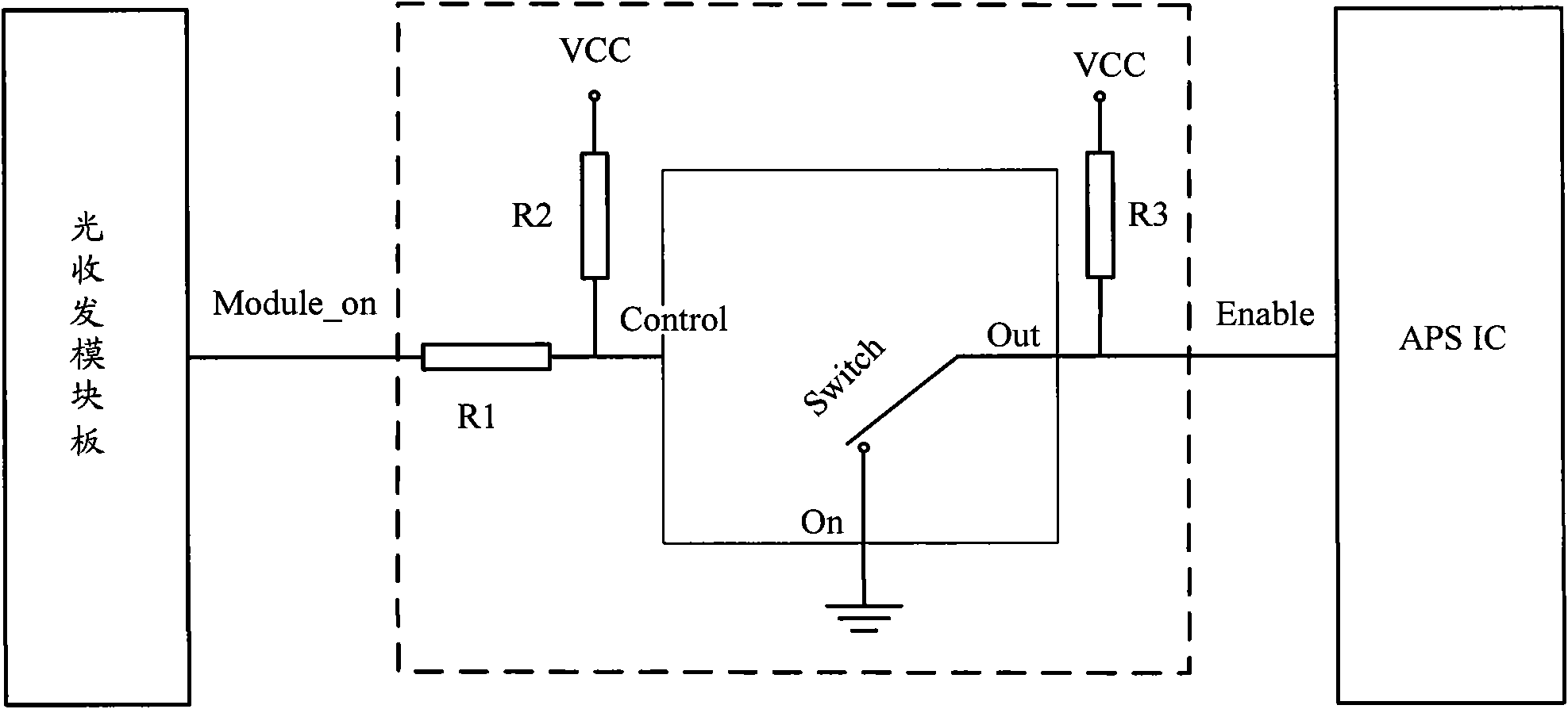
[0021] figure 2 It is a schematic diagram of the working principle of the optical transceiver module board and the APS power supply control device of the embodiment of the present invention, as figure 2 The circuit in the dotted box shown constitutes the main part of controlling the power supply of the APS integrated circuit (IC), and the power control device includes a first resistor (R1), a second resistor (R2), a third resistor (R3) and a switch Control element (Switch); where,

[0022] R1 is connected to any single board in-position detection signal and the input control port Control of the Switch; one end of R2 is connected to the first power supply VCC and the other end is connected to the Control end on the side of the R1; the signal input terminal In of the Switch is grounded ; The signal outp...


PUM


Abstract

The invention discloses a power controller with adaptation power supply. A power supply control circuit is additionally arranged so that a single plate can control a power supply of an adaptation power supply (APS) integrated circuit (IC) chip to supply electricity; when the single plate is not at a position, the output voltage of the APS control IC is 0 V; and when the single plate is at the position, the APS control IC normally works. The power controller with the adaptation power supply can effectively reduce the consumption of the electricity energy of communication equipment when the singe plate of the communication equipment is not at the position and can also enhance the compatibility of the APS power supply on optical single plates of different factories.

Description

technical field [0001] The invention relates to the power supply technology of electronic circuits, in particular to an adaptive power supply (APS, Adaptable Power Supply) power supply control device. Background technique [0002] In the 300Pin 10Gb Transponder (300-pin 10 Gigabit optical transceiver module) protocol, the single board is required to provide the APS function for the Transponder, and the supply voltage range of the APS power supply is 0.9V to 2.5V. [0003] figure 1 It is the functional block diagram of the connection between the APS and the optical transceiver module board in the existing 300Pin protocol, such as figure 1 As shown, the interface between APS and 300Pin optical transceiver module board includes the following four signals: APS_POWER (adaptive power supply), APS_SENSE (adaptive power supply sensing), APS_SET (adaptive power supply setting) and GND (working ground) signals. The power supplies power to the optical transceiver module through the A...

Claims


Application Information

Patent Timeline
Patent Type & Authority Applications(China)
IPC IPC(8): H02M3/10
Inventor 董强柴岩
Owner 宋华华
Learn More