Phase-locked loop circuit and control method thereof
A phase-locked loop and circuit technology, applied in the direction of automatic power control, electrical components, etc., can solve the problems affecting the stability of the phase-locked loop circuit 10, and achieve the effect of improving the stability
- Summary
- Abstract
- Description
- Claims
- Application Information
AI Technical Summary
Problems solved by technology
Method used
Image


Examples
Embodiment Construction
[0035] In order to make the object, technical solution and advantages of the present invention clearer, the present invention will be further described in detail below in conjunction with the accompanying drawings.
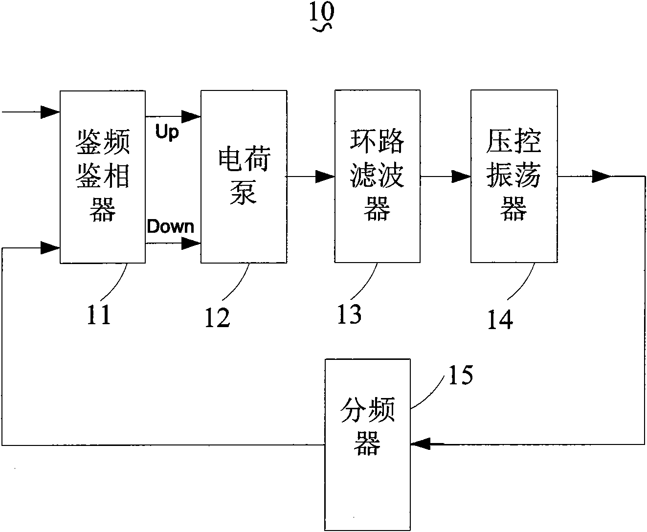
[0036] see figure 2 , figure 2 is a block diagram of a phase-locked loop circuit according to the first embodiment of the present invention. The phase-locked loop circuit 20 includes a frequency detector 21, a charge pump 22, a current mirror circuit 23, a loop filter 24, a loop filter resistor adjustment circuit 25, a voltage-controlled oscillator 26, and a frequency divider 27 connected in sequence. . The frequency and phase detector 21, the charge pump 22, the current mirror circuit 23, the loop filter 24, the loop filter resistance adjustment circuit 25, the voltage controlled oscillator 26, and the frequency divider 27 form a loop road.
[0037]The frequency division number of the frequency divider 27 can be preset, and the frequency division number of ...
PUM
 Abstract
Description
Claims
Application Information