Magnetic resonance inspecting apparatus
一种检查装置、磁共振的技术,应用在RF接收线圈领域,能够解决通道数增加等问题
- Summary
- Abstract
- Description
- Claims
- Application Information
AI Technical Summary
Problems solved by technology
Method used
Image
Examples
no. 1 Embodiment approach
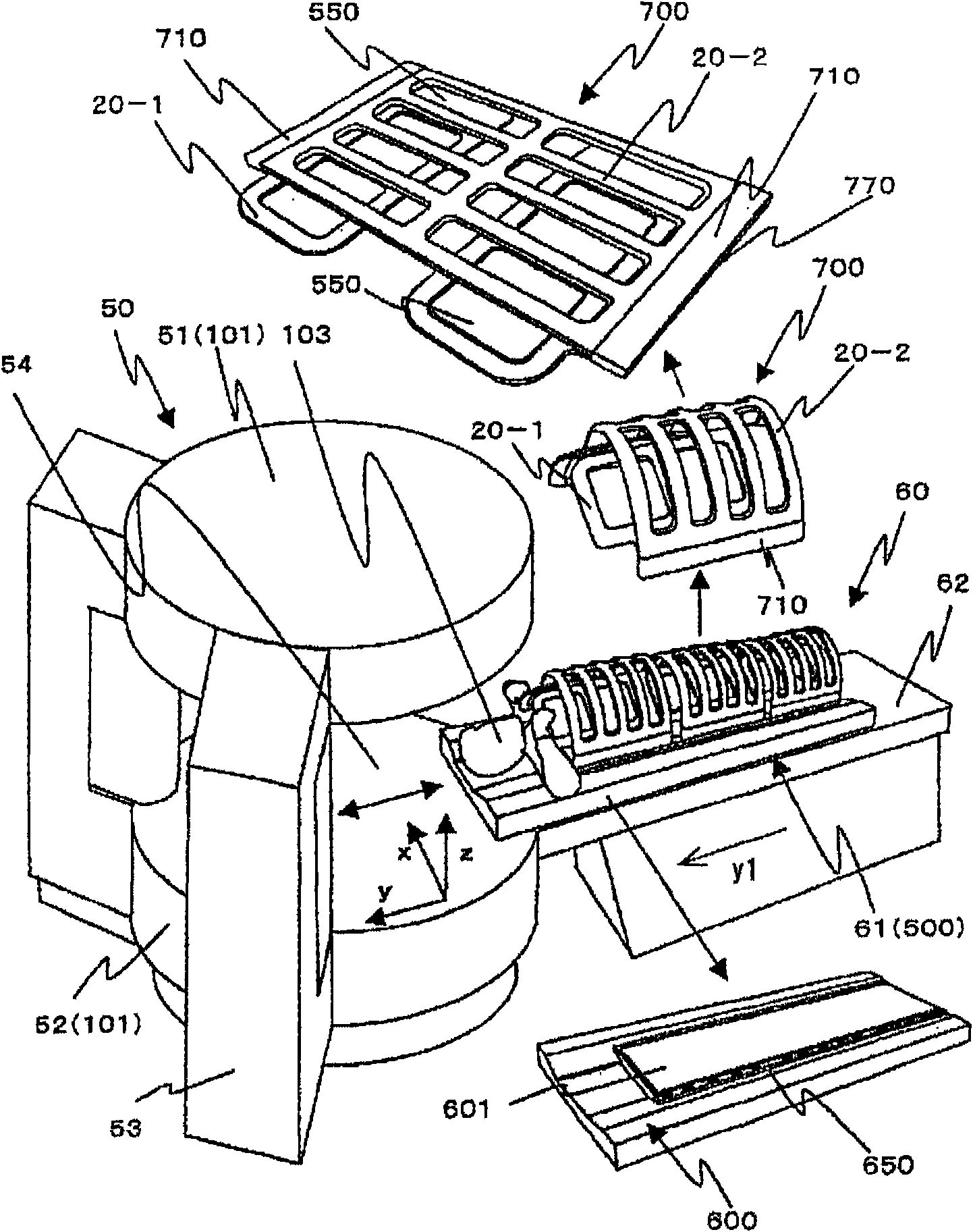
[0097] First refer to figure 1 A general configuration of the MRI apparatus according to this embodiment will be described. figure 1 It is an explanatory diagram showing a general configuration of an MRI apparatus.
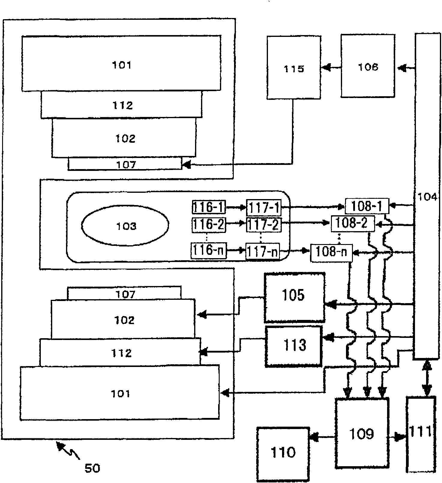
[0098] figure 1 Among them, the MRI apparatus related to this embodiment includes: an MRI apparatus body 50, which has a pair of magnets 101 arranged up and down to generate a static magnetic field in a vertical direction z indicated by an arrow z; The person (inspection object 103) is inserted into the static magnetic field in the vertical direction z of the MRI apparatus main body 50; a power supply unit not shown, a computer for processing images, and the like.
[0099] The MRI apparatus body 50 includes: an upper body 51 with a built-in magnet 101 , a lower body 52 , and a pillar portion 53 connecting and supporting the upper body 51 to the upper portion of the lower body 52 . A space of a predetermined size for inserting the test object 103 is formed betwe...
Embodiment
[0185] first, Figure 27 The layout diagram of the sub-coil after simulation and the G factor at this time are shown. Figure 27 (A) is an arrangement diagram of sub-coils in the y-z plane viewed from the x-axis direction, Figure 27 (B) is an arrangement diagram of sub-coils on the x-y plane viewed from the z-axis direction. Sub-coil 3-1 and 4-1 with Figure 4 The sub-coils of the same number are the same in the shown receiving coils. The sub-coils 6-1-1 and 6-1-2 are the most suitable deformation and appropriate overlapping of the conventional large-view coil (here, the saddle coil) 6-1, and the sub-coils 7-1-1 , 7-1-2 are set after the sub-coils 7-1 having sensitivity distribution in the left and right directions (hereinafter referred to as the RL direction, here the x direction) are deformed most appropriately and overlapped appropriately. And, the sub-coils 5-1-1 and 5-1-2 are moderately overlapping 2 sub-coils 5-1, and as Figure 12 As shown in (B), the two intersec...
no. 2 Embodiment approach
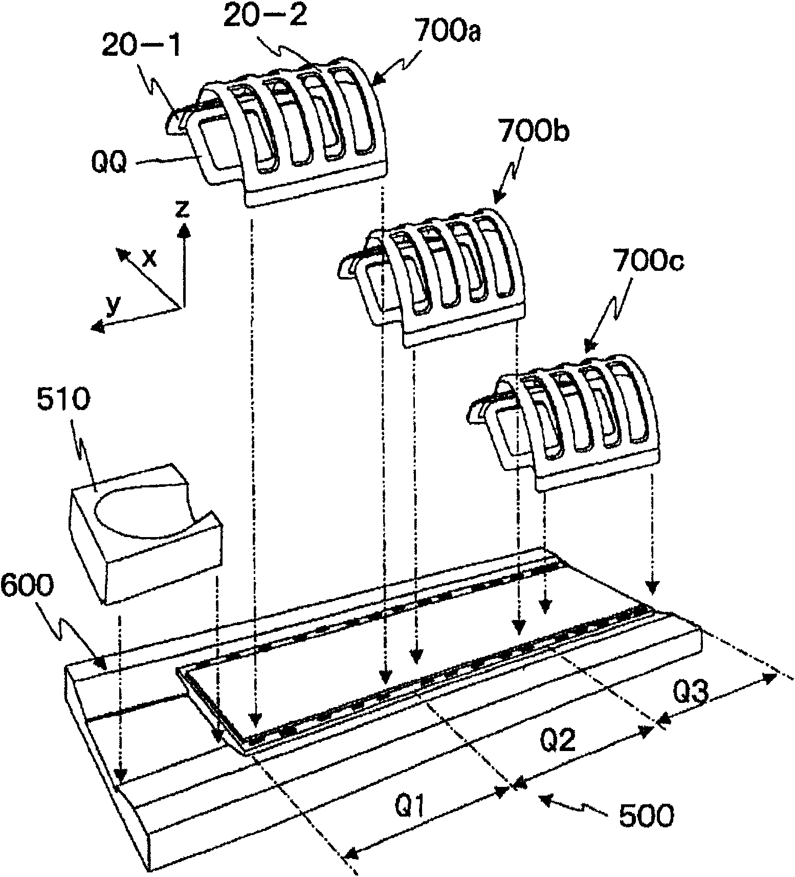
[0198] Refer below Figure 30 The external configuration of the receiving coil unit 103 according to the second embodiment will be described. Figure 30 Regarding the second embodiment, (A) is a perspective view of a state in which an inspection object is set, (B) is a cross-sectional view in a plane perpendicular to the body axis, and (C) is a perspective view of a state in which an outer support is opened. , (D) is an external view of the state after the inner support is opened.
[0199] In the figure, in this embodiment, the support supporting the coil conductor has a double structure consisting of an outer support 20-2 and an inner support 20-1. The outer support 20 - 2 can be divided into the back side and the chest side of the subject as shown in (C), and can be opened from one side of the test subject 103 . The inner support body 20 - 1 can be opened to both sides from the upper side (the ventral side when the person is supine) of the test subject 103 as shown in (D)....
PUM
 Abstract
Description
Claims
Application Information
 - R&D
- Intellectual Property
- Life Sciences
- Materials
- Tech Scout
- Unparalleled Data Quality
- Higher Quality Content
- 60% Fewer Hallucinations
Browse by: Latest US Patents, China's latest patents, Technical Efficacy Thesaurus, Application Domain, Technology Topic, Popular Technical Reports.
© 2025 PatSnap. All rights reserved.Legal|Privacy policy|Modern Slavery Act Transparency Statement|Sitemap|About US| Contact US: help@patsnap.com


