Thrust roller bearing
A thrust roller bearing and roller technology, applied in the field of thrust roller bearings, can solve the problems of undesired heat generation and increase of rotational torque, and achieve the effects of suppressing direct contact, suppressing torque increase, and enhancing reliability
- Summary
- Abstract
- Description
- Claims
- Application Information
AI Technical Summary
Problems solved by technology
Method used
Image

Examples
Embodiment 1
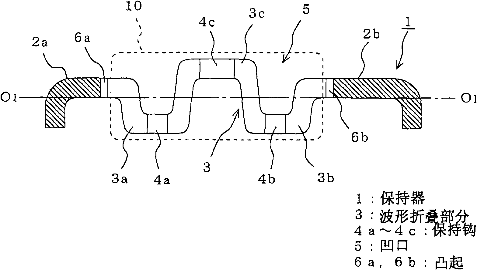
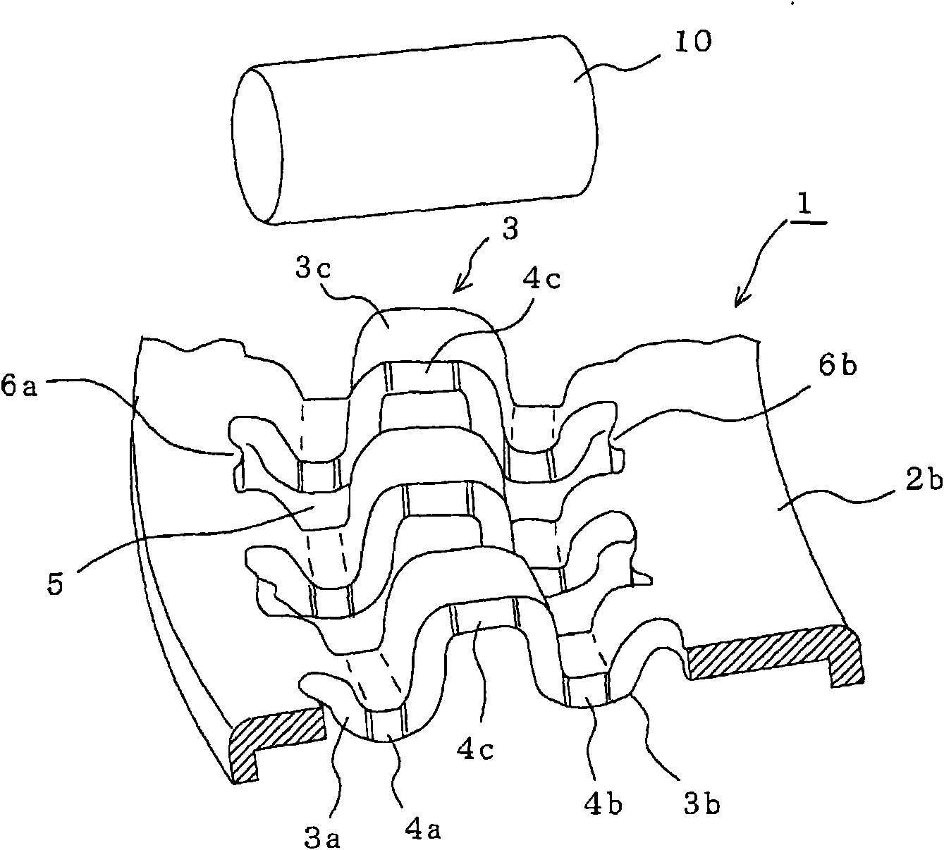
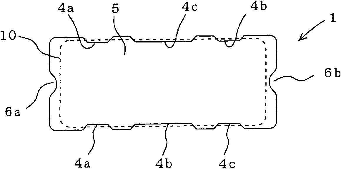
[0028] figure 1 is a sectional view of a cage of a thrust needle roller bearing as a thrust roller bearing according to Embodiment 1 of the present invention, figure 2 yes figure 1 An exploded perspective view of the cage and rollers in , and image 3 yes figure 1 Plan view of the notch in .
[0029] In the drawings, reference numeral 1 denotes a ring-shaped cage having a wave-folded portion 3 provided between an outer-diameter-side raceway guide portion 2a on the outer-diameter side and an inner-diameter side on the inner-diameter side. Between the raceway guide part 2b. This wave folded portion 3 includes an outer diameter side projecting portion 3a and an inner diameter side projecting portion 3b protruding substantially equally on one side, and on the other side protruding all the way beyond the outer diameter side raceway guide portion 2a and the inner diameter side raceway guide portion 2a. The middle protruding portion 3c at a higher position on the upper surfa...
Embodiment 2
[0035] Figure 5 is a sectional view of a cage of a thrust roller bearing according to Embodiment 2 of the present invention, and Figure 6 yes Figure 5 Plan view of the notch in .
[0036] In this embodiment, the retainer 1 is formed by integrally joining two annular plates 1a, 1b.
[0037] Between the outer diameter side raceway guide portions 2a, 2c and the inner diameter side raceway guide portions 2b, 2d of the two annular plates 1a, 1b, there are provided trapezoid-shaped protruding portions 3a, 3b folded in directions opposite to each other. . Between the raceway guide portions 2a, 2b and 2c, 2d are formed rectangular-shaped openings 5a, 5b that are long in the radial direction, and the two openings 5a, 5b are combined to form a roller for accommodating rollers. Notch 5 of 10. In addition, on both end faces in the radial direction of the opening 5a of one of the annular plates (for example, 1a), at approximately the center portion in the lateral direction thereof,...
PUM
 Abstract
Description
Claims
Application Information
 - R&D
- Intellectual Property
- Life Sciences
- Materials
- Tech Scout
- Unparalleled Data Quality
- Higher Quality Content
- 60% Fewer Hallucinations
Browse by: Latest US Patents, China's latest patents, Technical Efficacy Thesaurus, Application Domain, Technology Topic, Popular Technical Reports.
© 2025 PatSnap. All rights reserved.Legal|Privacy policy|Modern Slavery Act Transparency Statement|Sitemap|About US| Contact US: help@patsnap.com