
Icemaker, refrigerator provided therewith and ice making method

A refrigeration device and ice maker technology, which is applied to household refrigeration devices, cooling fluid circulation devices, ice making, etc., can solve the problems of the collection container occupying space, being difficult to handle, and unreliable separation of ice cubes from each other, so as to achieve reliable processing Effect

Inactive Publication Date: 2009-11-04
BSH BOSCH & SIEMENS HAUSGERAETE GMBH
View PDF6 Cites 5 Cited by
  • Summary
  • Abstract
  • Description
  • Claims
  • Application Information

AI Technical Summary

Problems solved by technology

In this way, however, only interconnected ice cubes can be obtained, and when removed from the mould, the ice cubes are not reliably separated from each other and thus occupy a large amount of space in the collection container and are very difficult to obtain. Difficult to handle

Method used


Image

  • Icemaker, refrigerator provided therewith and ice making method
  • Icemaker, refrigerator provided therewith and ice making method
  • Icemaker, refrigerator provided therewith and ice making method

Examples


Embodiment Construction

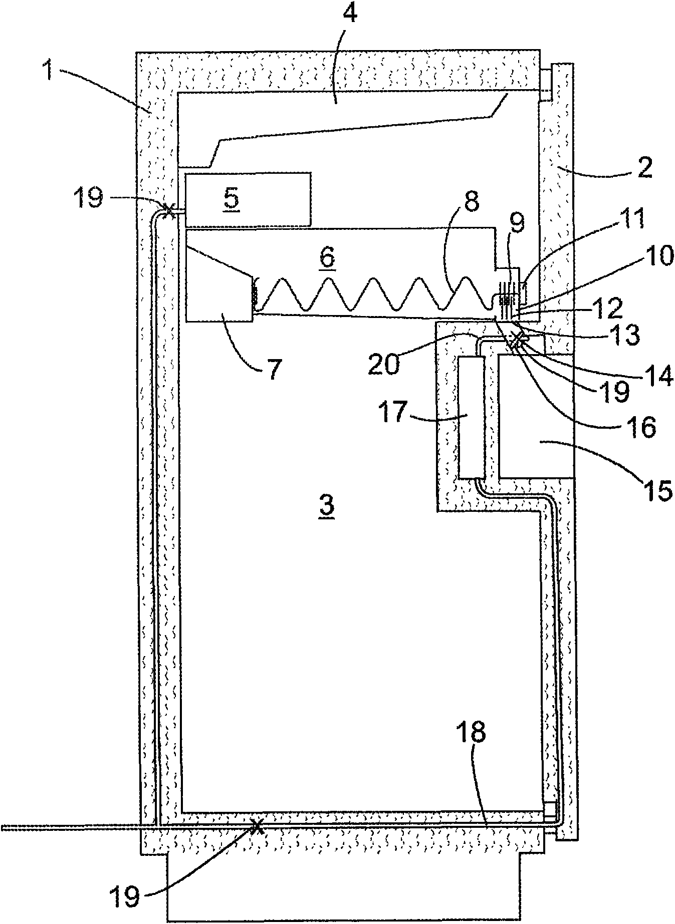
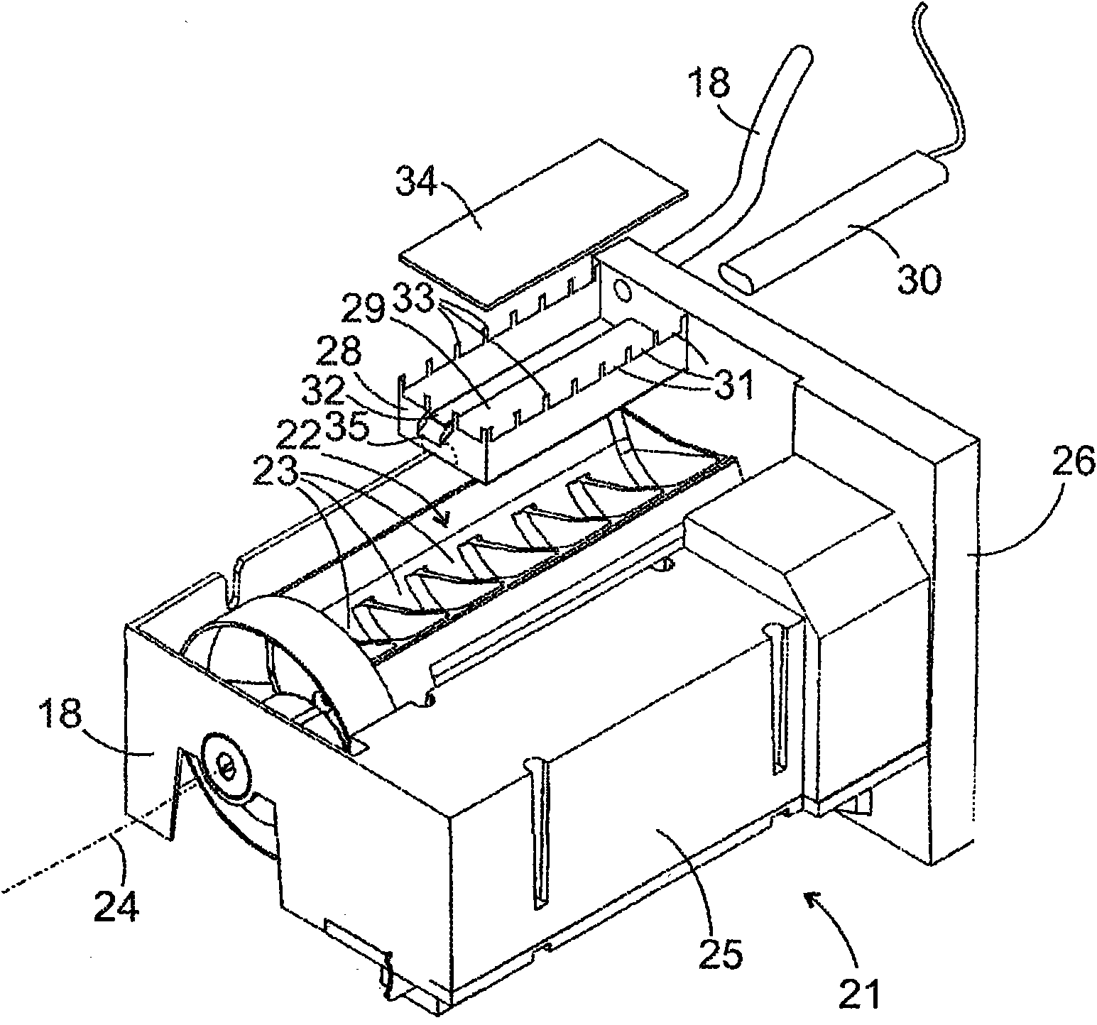
[0028] Such as figure 1 The refrigeration device shown in schematic sectional view has an insulating body 1 and a door 2 which define an interior space 3 . The inner space 3 is kept at a temperature below 0° C. by means of an evaporator housed in an evaporator compartment 4 in the upper region of the body 1 . An automatic ice maker 5 is arranged in the inner space 3 next to the evaporator chamber 4, so that cold air can be efficiently applied from the evaporator chamber 4 to the ice maker 5, wherein the automatic ice maker refers to figure 2 This will be described in more detail below.

[0029] Below the ice maker 5 is arranged a collection container 6 of the ice dispenser which receives the ice cubes discharged from the ice maker 5 . Collection container 6 extends over most of the depth of interior space 3 . An electric motor is accommodated in the rearward recess 7 of the collection container 6 , which serves to drive the stirring paddles 8 , which extend in the longitud...


PUM


Abstract

An icemaker for a refrigerator comprises a mould container (22) which may be filled with water, an air space (3) adjacent to a water level in the mould container (22) and an air humidifying device (28-35) for increasing the level of humidity in the air above the water level. Water is administered to the mould container (22), cooled and ice crystals form when a given crystallisation temperature of the water of below 0 DEG C is reached.

Description

technical field [0001] The invention relates to an ice maker comprising a shaped container, wherein said container can be filled with water and can be cooled to a temperature below 0° C. for making ice; The method of making ice realized by various types of ice makers. Background technique [0002] Most conventional ice makers utilize a shaped container within which a plurality of compartments are provided which communicate with each other when filled. Examples of ice makers of this type are disclosed in patent publications DE 4113767C2 and DE 2429392A1. [0003] There are two important reasons for providing connections between compartments of shaped containers. Firstly, the connection facilitates the automatic filling of the shaped container, since water can be delivered into the shaped container at a single point and diffused from there into the interconnected compartments. Another reason is the mechanism of ice formation. According to a process known as heterogeneous n...

Claims


Application Information

Patent Timeline
IPC IPC(8): F25C1/00F25D17/04F25D23/12F25C1/24
CPCF25C2600/04F25C2600/02F25C1/00F25D17/042F25C1/24F25C2400/14F25C2700/04F25D23/12F25C2400/10
Inventor S·霍尔策J·达姆拉特A·伦纳M·施皮尔曼莱特纳尔G·韦茨尔
Owner BSH BOSCH & SIEMENS HAUSGERAETE GMBH
Learn More