Main shaft universal bracket for engraving and milling machine

A universal bracket, engraving and milling machine technology, applied in the direction of support, metal processing mechanical parts, clamping and other directions, can solve the problems of inability to move each other, short use range, wear and so on

Inactive Publication Date: 2010-09-29
林仙根
View PDF6 Cites 0 Cited by
  • Summary
  • Abstract
  • Description
  • Claims
  • Application Information

AI Technical Summary

Problems solved by technology

However, the cutters of existing engraving and milling machines are directly installed under the main straight axis, so the cutters can only be used for vertical machining, and it is difficult to process surfaces with complex geometric shapes, such as curved surfaces and high-cut walls. Therefore, this The inventor developed the universal slope head of the engraving and milling machine, and applied for a Chinese patent, patent number 200510049990.9. The technical solution of this patent is to install a universally rotating ball joint in the fixed frame connected to the main shaft of the engraving and milling machine, the ball joint ( A softly curved rotating shaft is installed in the hollow), and the softly curved rotating shaft is connected to the rotating spindle of the engraving and milling machine, and the softly curved rotating shaft is connected to the clamping tool bar, which breaks the traditional situation of only vertical processing, and is suitable for various complex The machining of geometric shapes has a certain effect
However, it has the following disadvantages: First, the transmission force is transmitted from the main shaft of the engraving and milling machine to the clamping rod through the curved transmission shaft, which will cause wear and consume the transmission force, and the cur...

Method used


Image

  • Main shaft universal bracket for engraving and milling machine
  • Main shaft universal bracket for engraving and milling machine

Examples


Embodiment Construction

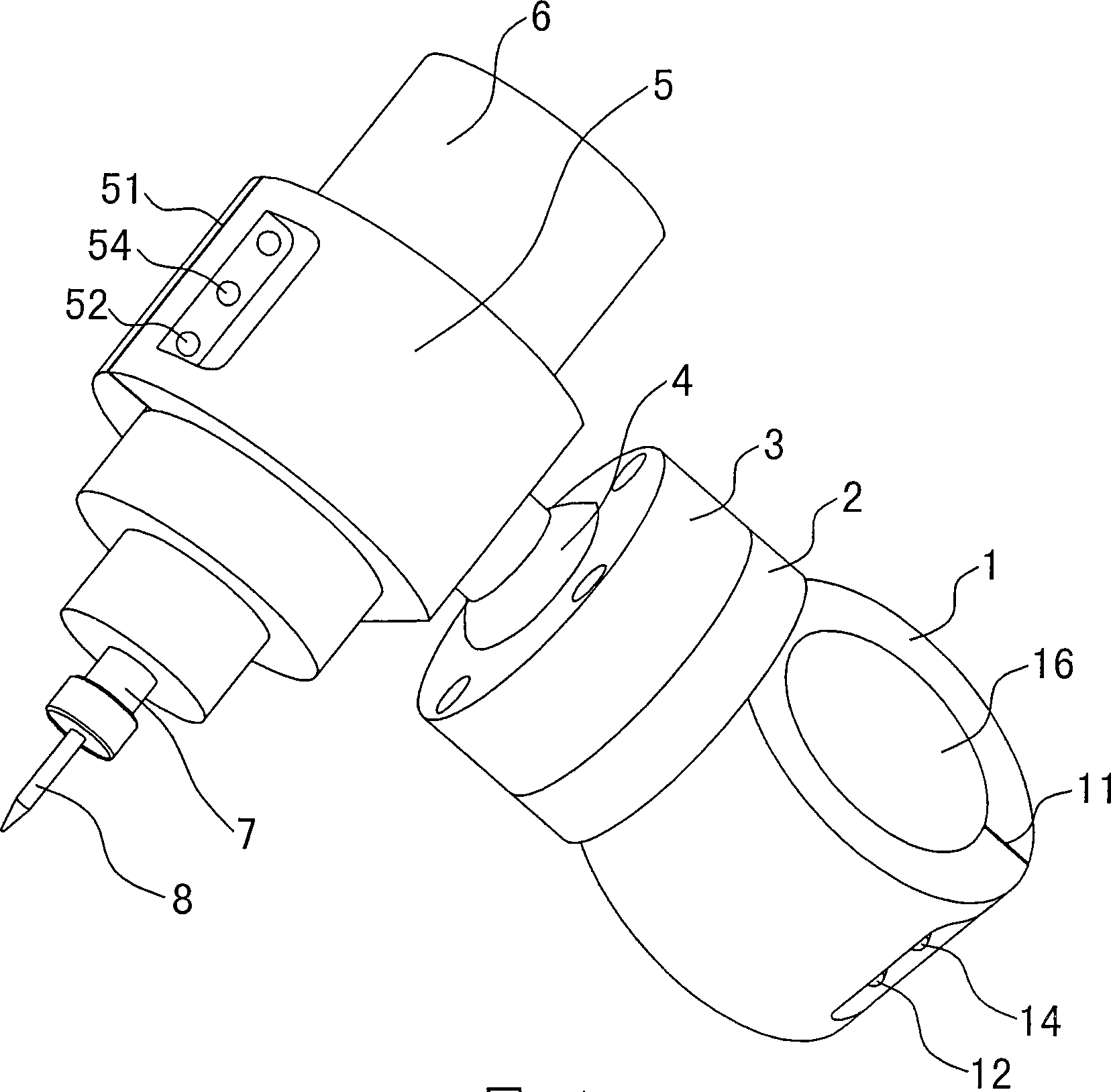
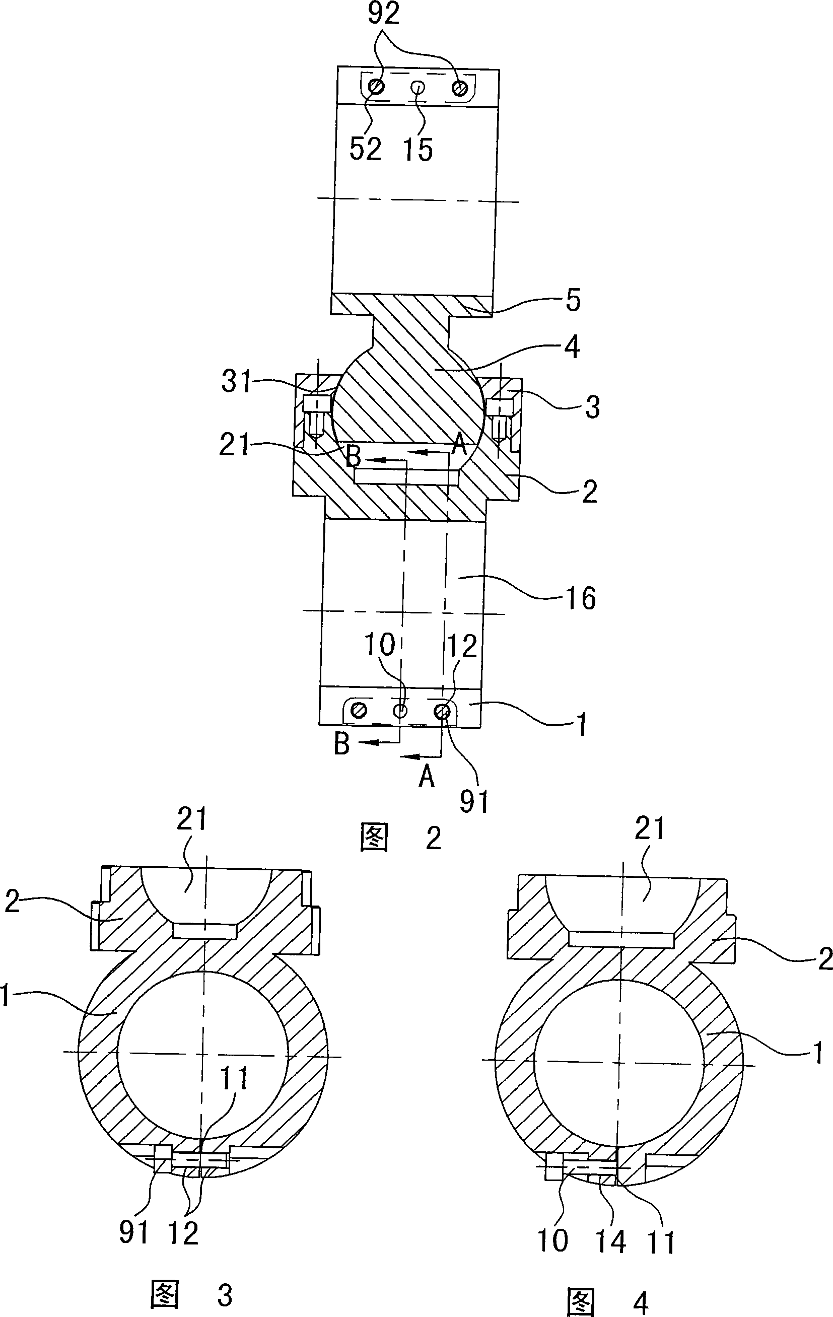
[0011] The invention discloses a universal support for the main shaft of an engraving and milling machine, such as figure 1 , figure 2 As shown, it is characterized in that it includes a fixed sleeve 1 that is movably installed on the head of the engraving and milling machine (the fixed sleeve is formed with a shaft hole 16, and the main shaft passes through the shaft hole of the fixed sleeve), the fixed sleeve is connected to the ball joint body 2, and the ball joint body Fasten the ball joint gland 3, the ball joint gland 3 and the ball joint body 2 are formed with ball sockets 31, 21, the ball sockets 31, 21 are equipped with universal ball joints 4, and the universal ball joints 4 move through the chuck 5 Install the motor 6, the motor shaft 7 is connected to the tool 8, the fixed sleeve 1 and the machine head are movable installation, there are many ways to install the fixed sleeve and the machine head, the most effective and simple one is to install it on the main shaft...


PUM


Abstract

The invention relates to a main shaft universal bracket for an engraving and milling machine, which is characterized by comprising a fixing sleeve movably arranged on the head of the engraving and milling machine, wherein the fixing sleeve is connected with a ball joint body which tightly fixes a ball joint press cover; the ball joint press cover and the ball joint body are internally provided with a ball socket, and the ball socket is internally provided with a universal ball joint; and the universal ball joint is movably provided with a motor through a clamping head, and a motor shaft is connected with a cutter. The fixing sleeve and the machine head are movably arranged, and the fixing sleeve can be arbitrarily rotated at 360 degrees around the machine head. The universal ball joint isrotated in the ball socket so as to ensure that the clamping head, the motor and the cutter also can be arbitrarily rotated at 360 degrees, and moreover, the angle of the ball joint and the ball socket can be inclined. The rotation of the clamping head, the motor and the cutter greatly increases the range of milling so as to ensure that the cutter can be flexibly rotated and can mill any surfaces.In addition, the fixing sleeve, the universal ball joint and the clamping head are connected with the motor so as to increase the working stroke and improve the processing capability. The motor directly drives the cutter, thus an intermediate link is reduced, and the transmitting power is enlarged.

Description

technical field [0001] The invention relates to an engraving and milling machine, in particular to a universal support for the main shaft of the engraving and milling machine, and belongs to the field of machine tools. Background technique [0002] Engraving and milling machines are widely used in the processing of metal materials such as plastic molds. However, the cutters of existing engraving and milling machines are directly installed under the main straight axis, so the cutters can only be used for vertical machining, and it is difficult to process surfaces with complex geometric shapes, such as curved surfaces and high-cut walls. Therefore, this The inventor developed the universal slope head of the engraving and milling machine, and applied for a Chinese patent, patent number 200510049990.9. The technical solution of this patent is to install a universally rotating ball joint in the fixed frame connected to the main shaft of the engraving and milling machine, the ball...

Claims


Application Information

Patent Timeline
IPC IPC(8): B23Q16/00B23Q3/00
Inventor 林仙根
Owner 林仙根
Why Eureka
Try Eureka