
Mixed-flow pump impeller

A mixed-flow pump and impeller technology, applied to pumps, pump components, components of pumping devices for elastic fluids, etc., can solve problems such as increased volume loss, serious gap cavitation, and decreased hydraulic efficiency

Inactive Publication Date: 2009-11-11
HARBIN ELECTRIC MASCH CO LTD
View PDF0 Cites 3 Cited by
  • Summary
  • Abstract
  • Description
  • Claims
  • Application Information

AI Technical Summary

Problems solved by technology

From the analysis of the performance of the unit, due to the excessively large fitting clearance of the leading edge of the blade, this structure leads to serious cavitation in the clearance, and also increases the volume loss, resulting in a decrease in hydraulic efficiency.

Method used


Image

  • Mixed-flow pump impeller
  • Mixed-flow pump impeller

Examples


Embodiment Construction

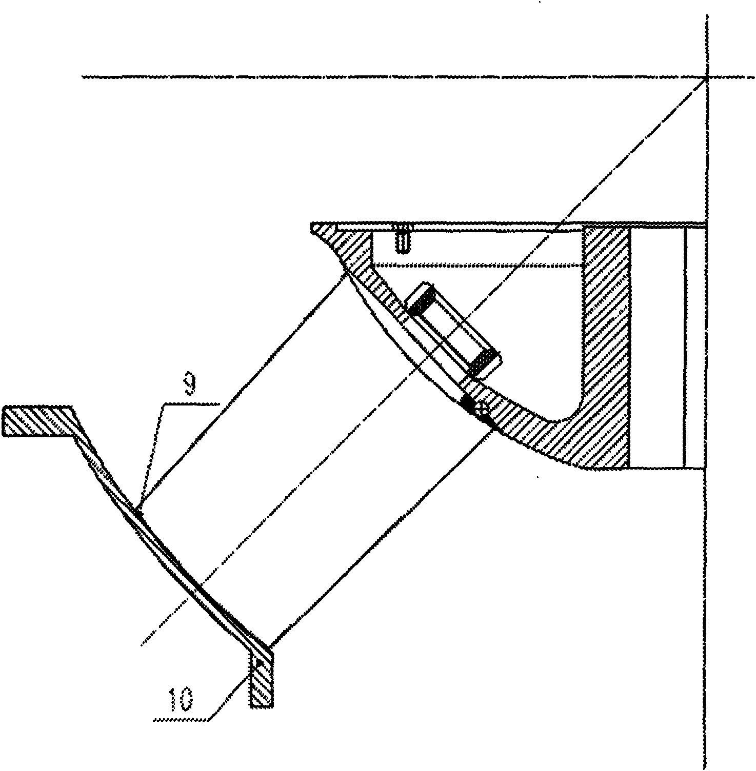
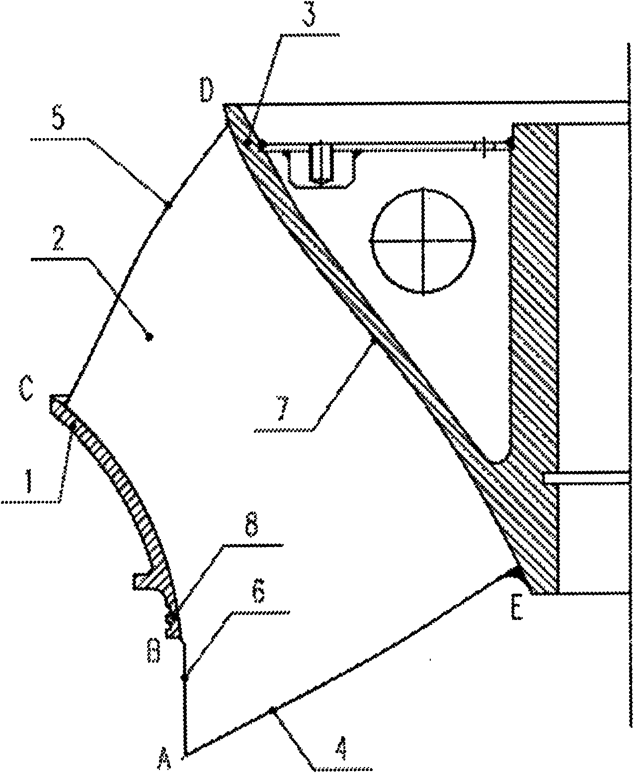
[0013] like figure 2 As shown, a mixed-flow pump impeller includes an incomplete front cover 1, a hub 3, and several blades 2 connected between the incomplete front cover 1 and the hub 3. The blades 2 have four peripheries, respectively The water inlet edge 4 of the blade, the water outlet edge 5 of the blade, the leading edge 6 of the blade on the side of the incomplete front shroud, and the trailing edge 7 of the blade on the side of the hub, the incomplete front shroud 1 and the leading edge 6 of the blade do not completely intersect, That is, the BC section of the leading edge 6 of the blade is within the annular cavity of the incomplete front shroud 1, the AB section of the leading edge 6 is exposed outside the annular cavity of the incomplete front shroud 1, and the hub 3 is completely connected to the blade trailing edge 7. Intersecting, the labyrinth groove 8 is located on the incomplete front cover plate 1, near the side of the blade water inlet 4, and the number of ...


PUM


Abstract

The invention relates to an incomplete front cover board mixed-flow pump impeller which comprises an incomplete front cover board, a wheel boss and a plurality of vanes connected between the incomplete front cover board and the wheel boss. The incomplete front cover board and the front edges of the vanes are incompletely crossed, that is, a part of the front edges of the vanes is arranged in an annular chamber of the front cover board and the other part thereof is exposed outside the annular chamber of the front cover board, therefore, the impeller is called incomplete front cover board mixed-flow pump impeller. By applying the impeller to the renovation project of a diagonal flow circulating water pump impeller of a large-sized turbo generator set, the impeller has the advantages of increased stiffness, improved reliability, high efficiency and energy conservation, and ensuring stable, economic and safe operation of the set.

Description

Technical field: [0001] The invention relates to a mixed flow pump impeller. technical background: [0002] At present, the circulating water pumps of large-scale turbogenerators in my country generally have problems such as low unit efficiency, serious cavitation, and poor stability, which seriously affect the economical and stable operation of the power station. In view of the unfavorable conditions such as large volume, high price and high transformation cost of the circulating pump unit, the transformation goal is achieved by replacing the impeller. Therefore, doing a good job in the energy-saving transformation of the circulating water pump of the large-scale steam turbine generator set and reducing the energy consumption level is the key to improving the economic efficiency of thermal power units in the country. efficient way to operate. [0003] like figure 1 Shown is a schematic diagram of the impeller and impeller chamber bushing of the oblique flow pump unit befo...

Claims


Application Information

Patent Timeline
IPC IPC(8): F04D29/18
Inventor 覃大清吴喜东张乐福曹大伟程宇坤
Owner HARBIN ELECTRIC MASCH CO LTD
Learn More