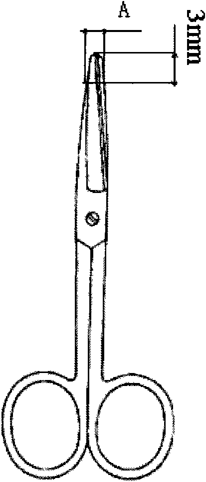
Automatic detection device for size of used position of surgical instrument and detection method thereof

An automatic detection device and surgical instrument technology, applied in the direction of measuring devices, optical devices, instruments, etc., can solve the problems of unavoidable human error, labor-intensive and low efficiency, and time-consuming manual visual inspection, so as to improve the qualified rate and Safety, high accuracy, and fast results

Inactive Publication Date: 2009-11-11
UNIV OF SHANGHAI FOR SCI & TECH
View PDF0 Cites 11 Cited by
  • Summary
  • Abstract
  • Description
  • Claims
  • Application Information

AI Technical Summary

Problems solved by technology

This traditional manual visual inspection is time-consuming, l

Method used


Image

  • Automatic detection device for size of used position of surgical instrument and detection method thereof
  • Automatic detection device for size of used position of surgical instrument and detection method thereof
  • Automatic detection device for size of used position of surgical instrument and detection method thereof

Examples


Embodiment Construction

[0038] The present invention will be further described below in conjunction with the accompanying drawings and embodiments.

[0039] Such as Figure 4 As shown, the automatic detection device for the size of the used part of the surgical instrument includes a computer 1, a camera 2, a light source lamp 3, a calibration gauge fixture 4, a width detection fixture 5, a height / thickness detection fixture 6, a camera fixing device 7, and a calibration gauge. Camera 2 consists of a CMOS image sensor and a CMOS camera.

[0040] Such as Figure 5 As shown, the camera fixing device 7 includes a camera frame 8, a guide rail slider 9, a guide rail 10, a guide rail base 11, and a detection platform 12. The helical tooth groove of tooth guide rail 10 connects fixed guide rail slide block 9, and guide rail slide block 9 is provided with camera frame 8, and camera frame 8 fixes camera 2, and guide rail base 11 front is provided with calibration gauge clamp 4, and platform 12 is fixed with ...


PUM

PropertyMeasurementUnit
Pixel sizeaaaaaaaaaa
Snraaaaaaaaaa
Sensitivityaaaaaaaaaa

Abstract

The invention relates to an automatic detection device for size of a used position of a surgical instrument and a detection method thereof. A video camera consists of a CMOS image sensor and a CMOS camera; the above of a detecting platform is fixedly connected with a helical-toothed upright post guide rail through a guide rail pedestal; a helical-toothed groove of the upright post guide rail is connected and fixed with a guide rail sliding block; the front of the guide rail sliding block is fixedly connected with a camera frame; the above of the camera frame is fixed with the video camera; the below of the video camera is fixed with a calibration gauge block fixture, the front of the calibration gauge block fixture is provided with a width detecting fixture, and the left side of the calibration gauge block fixture is provided with a height/thickness detecting fixture; an illuminator is placed on a platform under the video camera, and the center of a camera lens, the center of the calibration gauge block fixture, and the centers of the calibration gauge block and a detection position are in the same perpendicular line; and the video camera is connected with a computer through a USB 2.0 universal serial bus interface. The detection method comprises the following steps: 1, image acquisition; 2, system calibration; and 3, image processing, namely automatic positioning of the used position and edge detection of sub-pixel.

Description

technical field [0001] The invention relates to an instrument for automatically detecting the size of a used part of a surgical instrument, in particular to an automatic detection device and a detection method for the size of a used part of a surgical instrument based on the principle of machine vision. Background technique [0002] The size detection of surgical instruments is a very common and practical problem in the quality control of surgical instruments. At present, domestic surgical instrument manufacturers mainly adopt manual measurement methods, such as using vernier calipers, micrometers and other tools to measure the size of surgical instruments. This traditional manual visual inspection is time-consuming, labor-intensive and inefficient, and human error is inevitable. Contents of the invention [0003] The present invention is to provide an automatic detection device and detection method for the size of the used part of the surgical instrument. The device and ...

Claims


Application Information

Patent Timeline
IPC IPC(8): G01B11/00G01B11/02G01B11/06G01B11/03
Inventor 王殊轶张敏燕周颍葛斌孟青云郭世俊谢海明尹勋超高艳华韩露
Owner UNIV OF SHANGHAI FOR SCI & TECH
Why Eureka
Try Eureka