
Online monitoring and electricity testing method of switch cabinet lightning arrester and device for realizing same

A monitoring device and lightning arrester technology, which is applied in the field of monitoring and electrical inspection, can solve problems such as inability to accurately reflect the physical characteristics of the lightning arrester, unfavorable substation operator inspections, difficulty in meeting the high reliability requirements of high-voltage switchgear indirect electrical inspection, etc., to achieve discharge The effect of real and reliable times and good anti-electromagnetic field interference performance

Inactive Publication Date: 2009-11-11
ZIYANG POWER SUPPLY COMPANY STATE GRID SICHUAN ELECTRIC POWER +1
View PDF1 Cites 26 Cited by
  • Summary
  • Abstract
  • Description
  • Claims
  • Application Information

AI Technical Summary

Problems solved by technology

However, in practical applications, there is a lack of non-stop detection methods for surge arresters in high-voltage switchgear and double indirect electrometry devices that are effective for equipment on the side of high-voltage switchgear.
The current indoor switchgear has the following problems: 1. Arrester counters, leakage ammeters or operating status indicators are installed in the high-voltage switchgear, which is not conducive to the patrol inspection of substation operators
2. It is not easy to maintain and replace after the failure of the display part, and it needs to be maintained and replaced after the switch cabinet and the outlet side are powered off
3. Judging the operation status of the arrester by adding the capacitive current and the resistive current of the full leakage current of the arrester can not accurately reflect the physical characteristics of the operation status of the arrester
4. The arrester counter can only record the number of actions of the arrester, but cannot record the time of each action of the arrester, which is not conducive to the analysis of accidents
5. The live display device on the outlet side of the existing switch cabinet can only reflect the live state of the equipment with the indicator light or the display of whether there is electricity or no electricity, but cannot reflect the actual voltage value of the equipment in a more accurate, real-time and dynamic manner, so as to give operators accurate information. Judging whether it is live brings a lot of inconvenience
For example, when the switch knife switch on the line side is disconnected, there is a generator on the line to generate power and send back the electric energy, but the voltage sent back is low, which makes the indication of the live indicator device not obvious, which leads to vicious errors in the grounding of the live puller. Operation or even life casualty accident etc.
6. Due to the existing indirect electric inspection device with only a single principle and circuit, this is also the biggest defect in the live display device of the switchgear at present. high electrical reliability requirements
[0003] The application date is January 26, 2002, the announcement number is CN1267798C, and the name is "a Chinese invention patent for a switch cabinet with a built-in monitoring device or a switch cabinet device, which discloses a switch cabinet with a monitoring device inside. The key solution is to monitor and transmit the temperature and humidity in the switchgear, but it has not been able to solve the above problems

Method used


Image

  • Online monitoring and electricity testing method of switch cabinet lightning arrester and device for realizing same
  • Online monitoring and electricity testing method of switch cabinet lightning arrester and device for realizing same
  • Online monitoring and electricity testing method of switch cabinet lightning arrester and device for realizing same

Examples


Embodiment Construction

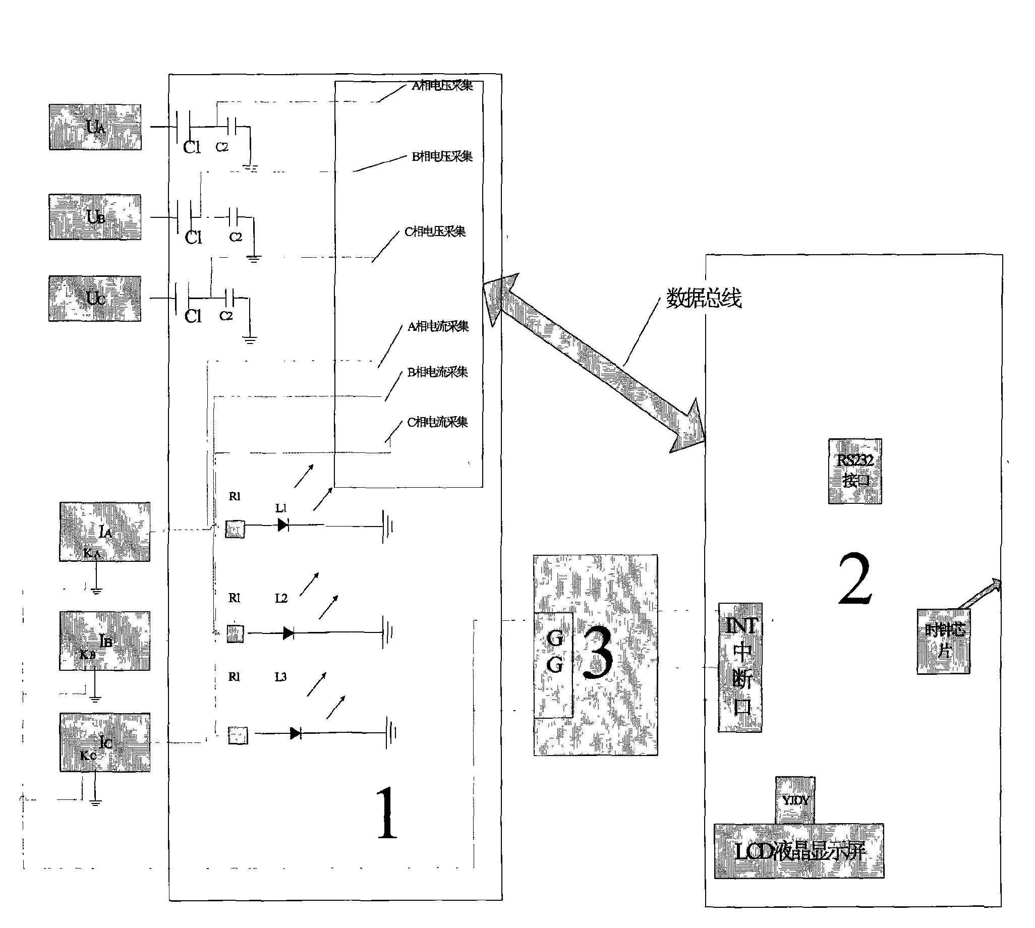
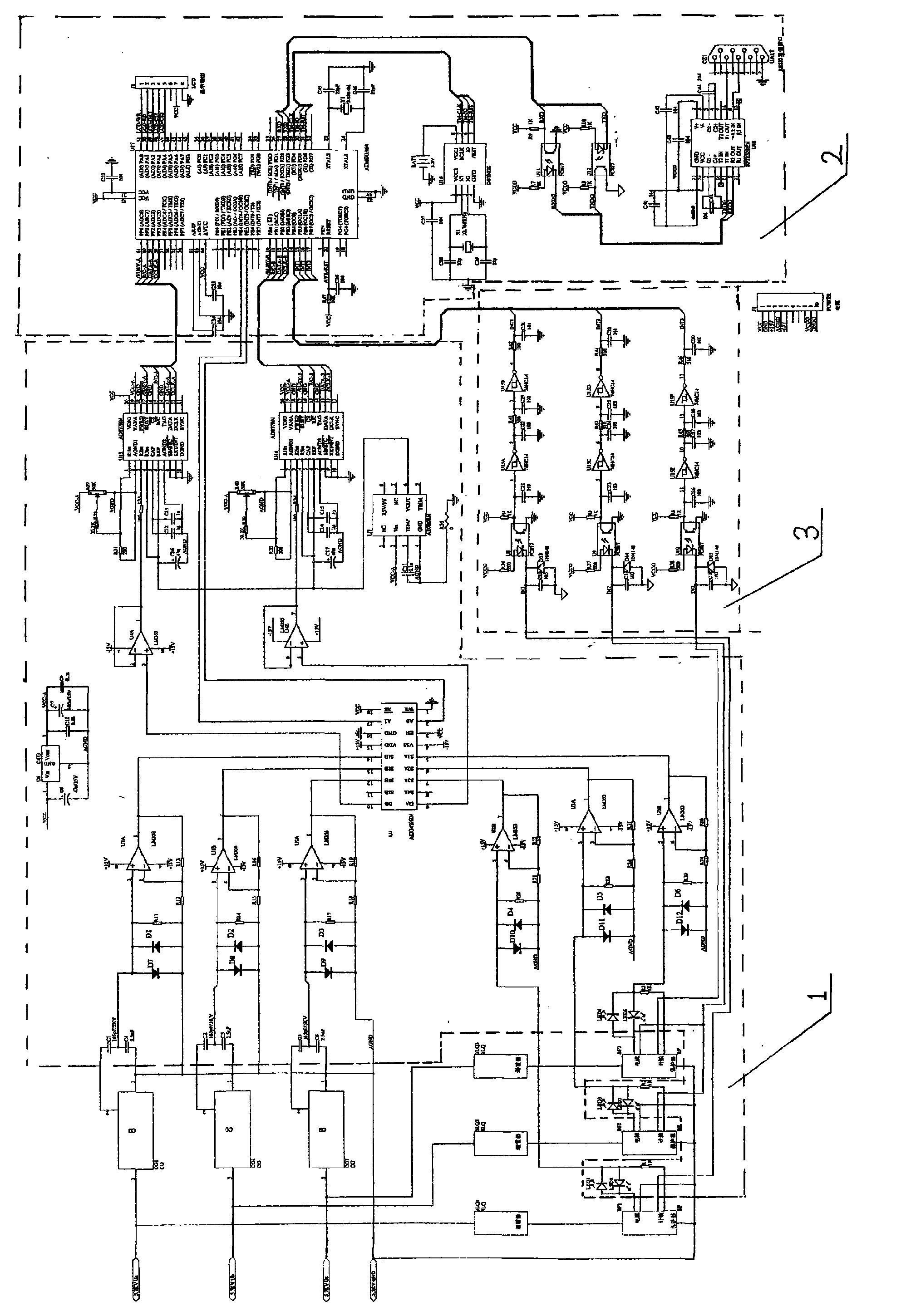
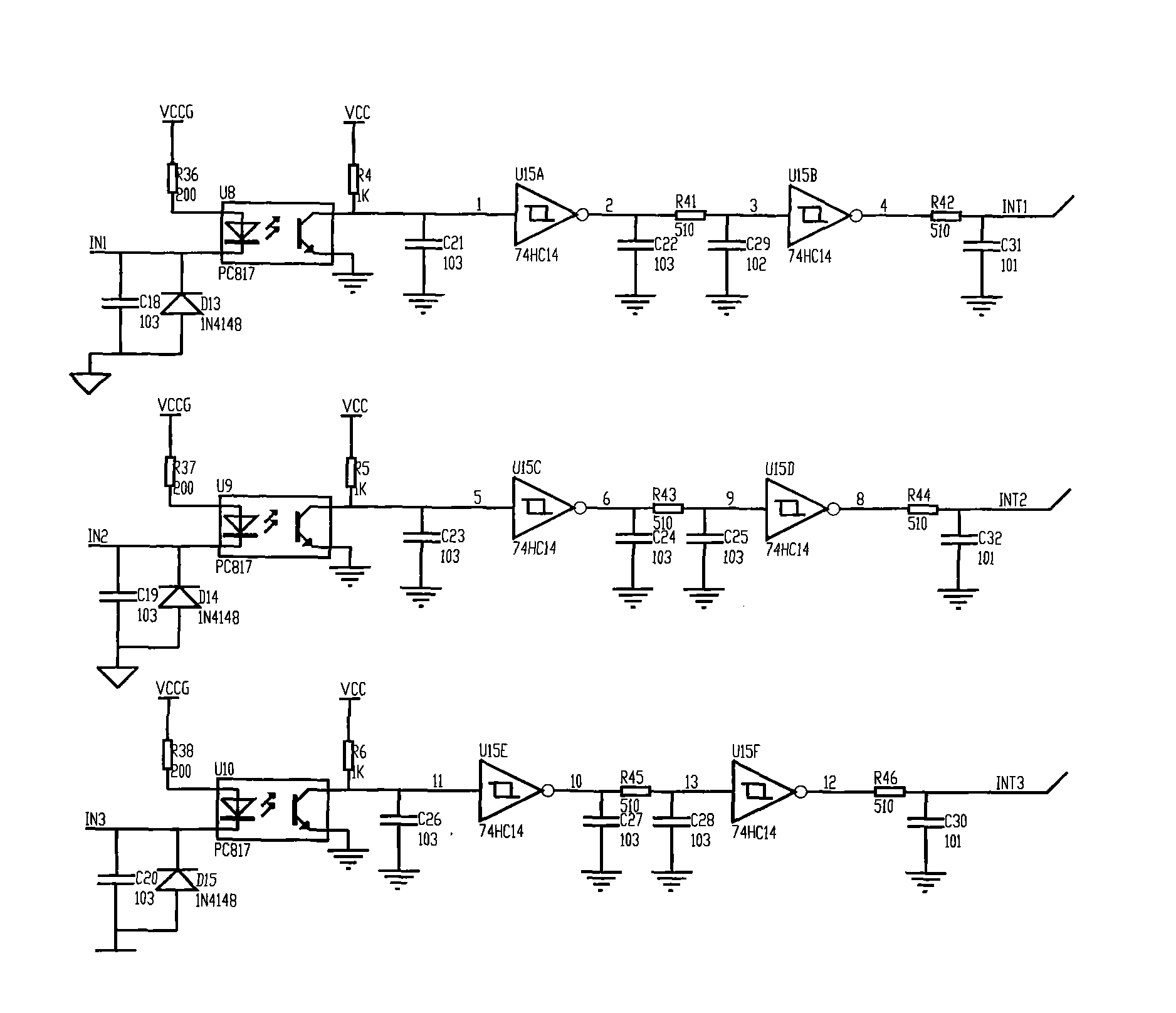
[0046] The present invention will be further elaborated below in conjunction with the accompanying drawings. Introduce in detail the specific implementation of the method device for realizing the present invention: as figure 1 and figure 2 As shown, the device is divided into three units,

[0047] The first unit is the voltage and current acquisition unit 1, which is connected with the voltage and current signal input unit with lines, and is responsible for collecting the current and voltage analog signals, and at the same time performs A / D sampling and conversion on the analog, and digitally stores the processed data in the output on the data bus;

[0048] The second unit is an MCU with a liquid crystal display device 2. The MCU is connected to the first part through a data bus, and is responsible for sequentially reading data through a specified data bus format and performing fast Fourier change calculations and integral calculations for corresponding three-phase voltage ...


PUM


Abstract

The invention discloses an online monitoring method of a switch cabinet lightning arrester, a double indirect electricity testing method of equipment at the wire outgoing side of a high-voltage switch cabinet, and a device for realizing the method. In the method and a matched device thereof, a voltage signal and a current signal are simultaneously taken as signal monitoring input signals of the switch cabinet lightning arrester, the input signal is subjected to digitalized processing so as to display a specific value of a primary voltage of the equipment at the wire outgoing side in real time, to be capable of collecting the action times of the lightning arrester in a switch cabinet, the accurate time of each action, the leakage full current and resistance current of each phase of the lightning arrester, and automatically recording the values of the full current and resistance current in a set time. The device is provided with three current indicating lamps which are directly connected with a three-phase lightning arrester. The current indicating lamps can be turned on by the leakage current of the lightning arrester directly so as to achieve the purpose of indicating electricity. The leakage current indicating lamps of the lightning arrester and line primary voltage form double indirect electricity testing so as to reach the standard of switch cabinet indirect electricity testing.

Description

technical field [0001] The invention relates to a method of monitoring and electric inspection, in particular to a method for on-line monitoring of a high-voltage switchgear arrester, a method for double indirect electric inspection of equipment on the outlet side of a high-voltage switchgear, and a device for realizing the method. Background technique [0002] 10kV-35kV high-voltage switchgear is the most commonly used electrical equipment in substations. However, in practical applications, there is a lack of non-stop detection means for surge arresters in high-voltage switchgear and effective double indirect electrometry devices for side equipment in high-voltage switchgear. The current indoor switchgear has the following problems: 1. Arrester counters, leakage ammeters or operating status indicators are installed in the high-voltage switchgear, which is not conducive to the patrol inspection of substation operators. 2. It is not easy to maintain and replace after the dis...

Claims


Application Information

Patent Timeline
IPC IPC(8): G01R31/00G01R19/25G01R19/15
Inventor 海何兵张雷张苏川欧居勇李海峰
Owner ZIYANG POWER SUPPLY COMPANY STATE GRID SICHUAN ELECTRIC POWER
Learn More