Touch-control panel and touch sensing method and application thereof

A touch panel, light sensing technology, applied in the direction of instrument, electrical digital data processing, data processing input/output process, etc., can solve the problems of misjudgment, gesture mutual shading, etc., to avoid misjudgment and improve touch control. The effect of accuracy

Inactive Publication Date: 2009-11-11
AU OPTRONICS CORP
View PDF0 Cites 17 Cited by
  • Summary
  • Abstract
  • Description
  • Claims
  • Application Information

AI Technical Summary

Problems solved by technology

Therefore, when performing multi-point or multi-finger (multi-finger) operat...

Method used


Image

  • Touch-control panel and touch sensing method and application thereof
  • Touch-control panel and touch sensing method and application thereof
  • Touch-control panel and touch sensing method and application thereof

Examples


Embodiment Construction

[0026] The following descriptions of the various embodiments refer to the accompanying drawings to illustrate specific embodiments in which the present invention can be practiced. The directional terms mentioned in the present invention, such as "up", "down", "front", "back", "left", "right", "inside", "outside", "side", etc., are for reference only The orientation of the attached schema. Therefore, the directional terms used are used to illustrate and understand the present invention, but not to limit the present invention.

[0027] In the following embodiments, the same parts are denoted by the same symbols in different drawings.

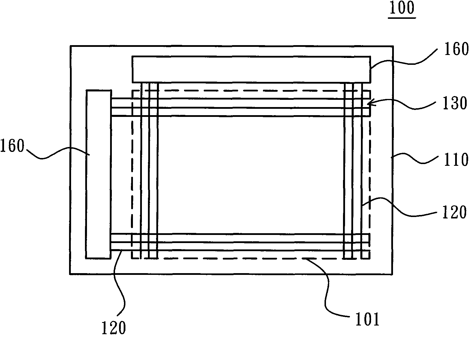
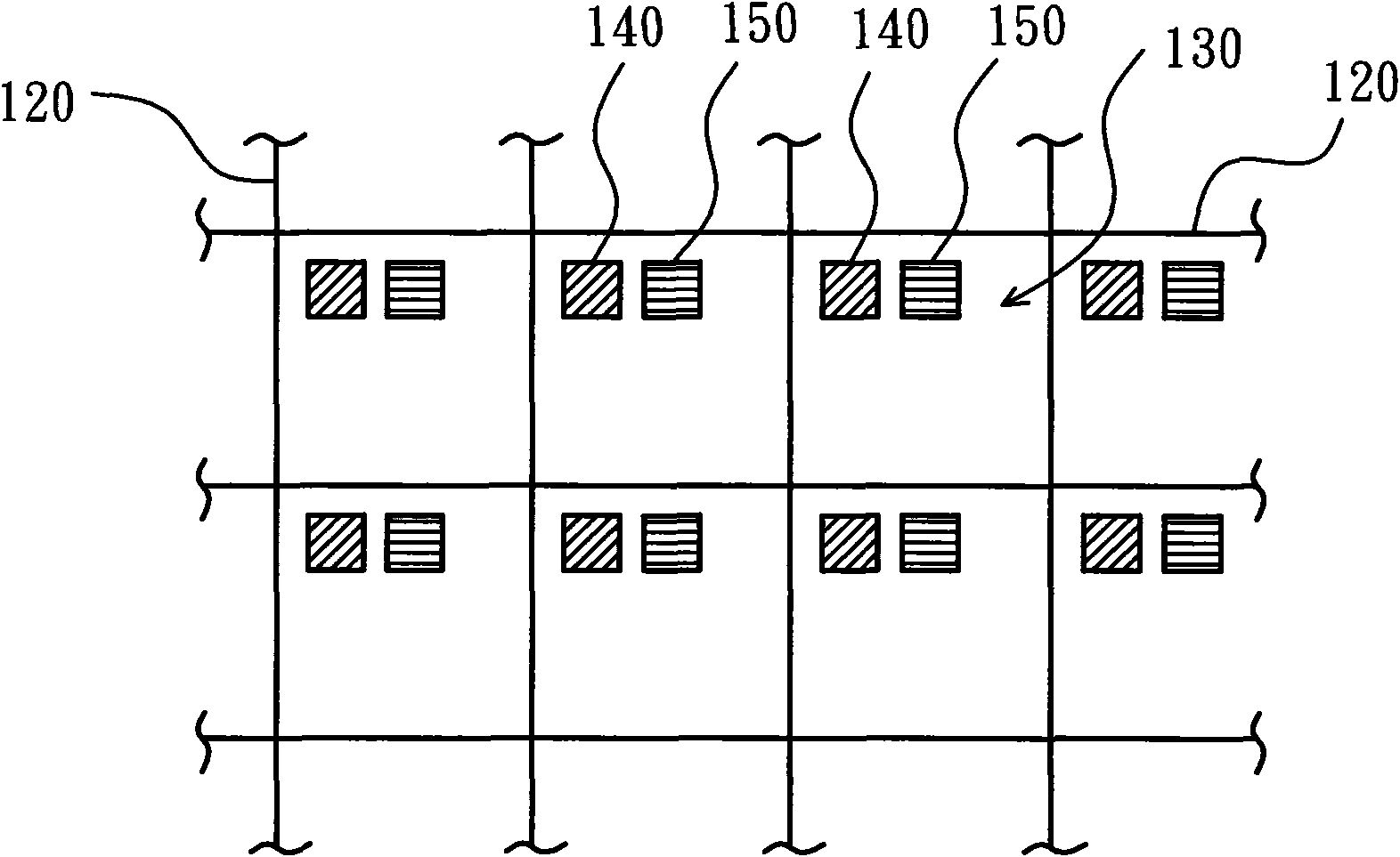
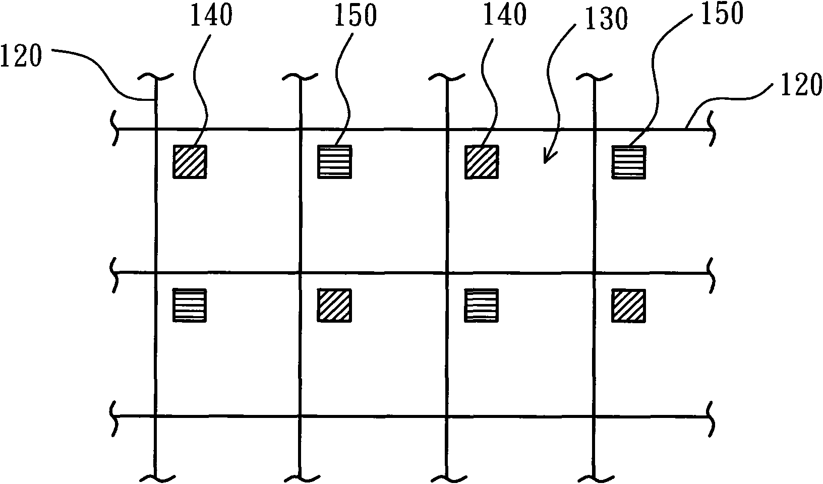
[0028] Please refer to figure 1 , which shows a schematic top view of a touch panel according to an embodiment of the present invention. The touch panel 100 of this embodiment can be an externally attached touch panel or a touch panel integrated in a display device (such as an embedded touch panel), and the display device can be, for example, a...


PUM


Abstract

The invention provides a touch-control panel and a touch sensing method and a display device applied. The touch panel comprises a substrate, a pixel, a visible light sensing element and an invisible light sensing element. The pixel is formed on the substrate, the visible light sensing element is arranged in the pixel for sensing visible light, and the invisible light sensing element is arranged in the pixel for sensing invisible light. The invention can avoid the situation of misjudge and can be applied in the environment of low light intensity or dark state.

Description

technical field [0001] The present invention relates to a touch panel, in particular to a touch panel, a touch sensing method thereof, and a display device applied thereto. Background technique [0002] Various current electronic devices have widely used touch technology as their input method, whereby the user can use a finger or a stylus to touch the display panel to simultaneously or simultaneously transmit information and display information. Therefore, buttons, keyboards or sliders that must be configured on conventional electronic devices can be omitted. [0003] Taking the optical touch panel as an example, it uses the principle of light receiving and blocking to sense the touch of foreign objects. The optical touch panel includes a plurality of light sensors disposed on the panel, wherein the light sensors are used to sense visible light. When the ambient light illuminates the light sensor, a photocurrent can be generated; otherwise, when the light sensor is covered...

Claims


Application Information

Patent Timeline
IPC IPC(8): G02F1/133G06F3/033G06F3/0354
Inventor 谢宗贤洪集茂孙伟珉
Owner AU OPTRONICS CORP
Why Eureka
Try Eureka