Supercharge Your Innovation With Domain-Expert AI Agents!

Light-emitting device and illumination apparatus using the same

A light-emitting device and light-emitting part technology, applied in the direction of lighting and heating equipment, components of lighting devices, semiconductor devices of light-emitting elements, etc., can solve problems such as hindering the control of light distribution

Inactive Publication Date: 2009-11-11
PANASONIC CORP
View PDF1 Cites 10 Cited by
  • Summary
  • Abstract
  • Description
  • Claims
  • Application Information

AI Technical Summary

Problems solved by technology

[0005] However, in the light-emitting device 100 described above, part of the light emitted from the light-emitting portion end 102a of the light-emitting element 102 on the opening side of the light-collecting reflector 103 is not reflected by the paraboloid of revolution surface 103a, so that part of the light emitted by the light-emitting element 102 is not reflected. Will become parallel light, which may prevent control of light distribution

Method used


Image

  • Light-emitting device and illumination apparatus using the same
  • Light-emitting device and illumination apparatus using the same
  • Light-emitting device and illumination apparatus using the same

Examples


no. 1 example

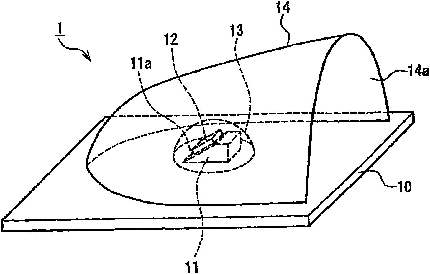
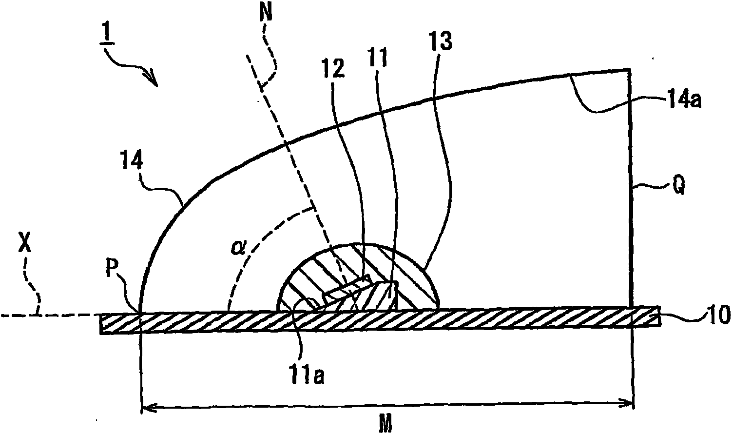
[0048] Figure 1A is a schematic perspective view of a light emitting device according to a first embodiment of the present invention, Figure 1B Yes Figure 1A A schematic cross-sectional view of the light-emitting device shown in .

[0049] like Figure 1A and 1B As shown in each figure, the light-emitting device 1 includes a substrate 10, a base 11 disposed on the substrate 10, a light-emitting element 12 disposed on one main surface 11a of the base 11, a seal formed of a translucent material and covering the light-emitting element 12. The resin portion 13 , and the light distribution control reflector 14 provided to surround the light emitting element 12 and the sealing resin portion 13 . The material for the substrate 10 is not particularly limited, and examples thereof that can be used include the following materials: single crystals such as sapphire, Si, GaN, AlN, ZnO, SiC, BN, and ZnS; ceramics such as Al 2 o 3 , AlN, BN, MgO, ZnO, SiC and C or mixtures thereof; ...

no. 2 example

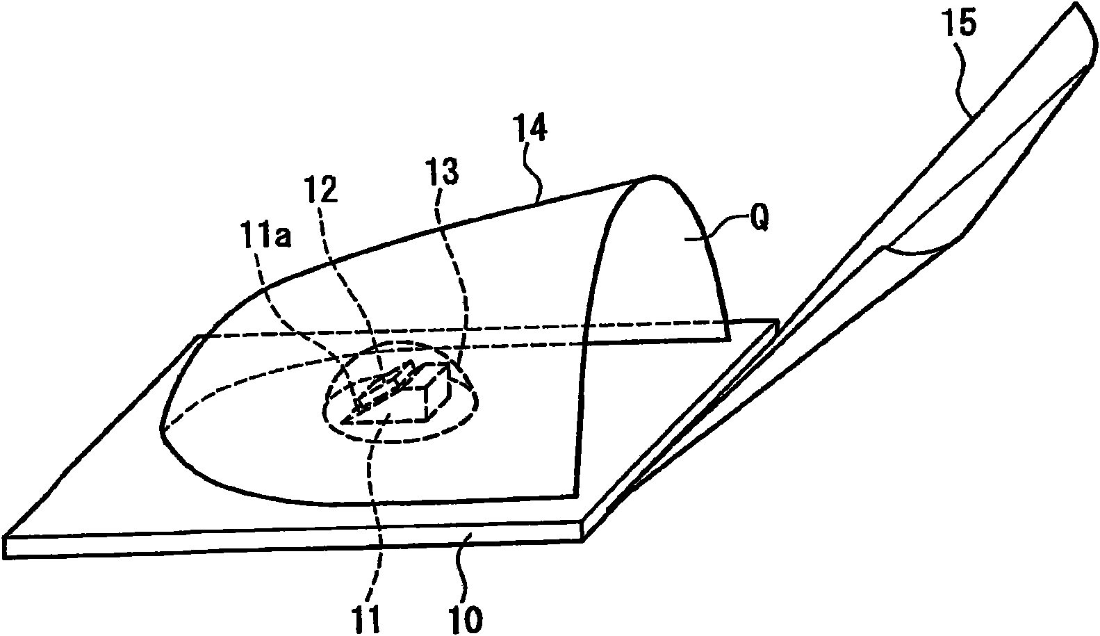
[0055] Figure 3A is a schematic perspective view of a light emitting device according to a second embodiment of the present invention, Figure 3B Yes Figure 3A A schematic cross-sectional view of the light-emitting device shown in .

[0056] like Figure 3A and 3B As shown in each figure, the light-emitting device 2 includes four cylindrical bodies 20, a base 11 disposed at the end of each cylindrical body 20, a light-emitting element 12 disposed on a main surface 11a of the base 11, and a cover light-emitting element 12. The spherical sealing resin portion 13, and the light distribution control reflector 21 arranged to surround the light emitting element 12 and the sealing resin portion 13. The light distribution control reflector 21 is a substantially paraboloid of revolution having an axis X in the area surrounded by the four cylindrical bodies 20 . The material used for the columnar body 20 is not particularly limited, and a material similar to the material of the s...

no. 3 example

[0060] Figure 4 is a schematic cross-sectional view of a light emitting device according to a third embodiment of the present invention. The light emitting device of this embodiment is a modified example of the first embodiment.

[0061] like Figure 4 As shown, the light-emitting element 12 is arranged at the substantially focal position of the surface 14a of a substantially paraboloid of revolution, and the substrate 11 also functions as a reflector. In addition, the upper surface 11a of the substrate 11 is inclined with respect to the X-axis of a substantially paraboloid of revolution so that the optical axis L1 of the light-emitting element 12 (the optical axis of the light-emitting part) is oriented approximately The vertex P of the paraboloid of revolution is inclined. Thus, similarly to the light emitting device 1 of the first embodiment, control of light distribution can be facilitated.

[0062] In this embodiment, the light emitting part is constituted by the lig...


PUM


Abstract

A light-emitting device (1) includes: a base (11); a light-emitting element (12) that is disposed on one principal surface (11a) of the base (11); and a light distribution control reflector (14) that is disposed so as to surround the light-emitting element (12). The light distribution control reflector (14) is at least part of a substantial paraboloid of revolution, and a substantial paraboloid-of-revolution surface (14a) that constitutes an inner surface of the light distribution control reflector (14) is a light-reflecting surface for collecting light emitted from the light-emitting element (12). The light-emitting element (12) is disposed at a position of a substantial focal point of the substantial paraboloid-of-revolution surface (14a), and a normal (N) to the one principal surface (11a) of the base (11) is inclined toward a vertex (P) of the substantial paraboloid of revolution with respect to a direction orthogonal to an axis (X) of the substantial paraboloid of revolution. Thus, the light-emitting device (1) can be provided in which light distribution control can be facilitated.

Description

technical field [0001] The present invention relates to a light emitting device including a light emitting element and lighting equipment using the light emitting device. Background technique [0002] Light emitting elements such as light emitting diodes (hereinafter referred to as "LEDs") are used in various light emitting devices. Compared with existing light sources using electric discharge and radiation, LEDs not only have a smaller size and higher efficiency, but have also recently been developed to provide greater luminous flux, thereby allowing them to replace existing light sources. [0003] Furthermore, when combined with an optical system with reflective and lens functions, LEDs can control the radiation pattern of the emitted light. For example, JP 2005-32661A proposes a light emitting device capable of extracting light emitted from a light emitting element as parallel light using a light collecting reflector constituted by a partial shape of a paraboloid of revo...

Claims


Application Information

Patent Timeline
Patent Type & Authority Applications(China)
IPC IPC(8): F21S8/10F21Y101/02H01L33/00H01L33/54H01L33/60H01L33/62
CPCF21K9/00H01L33/54H01L2924/01046H01L33/60H01L2924/01079H01L2924/01025H01L24/17H01L2224/16H01L2924/01063F21S48/1335H01L2924/01322F21S48/145H01L2924/01029H01L2924/0102H01L2924/01057F21V7/0025H01L33/62H01L2924/01012F21S48/1241F21Y2101/02F21S8/02F21V7/06F21S48/115H01L2924/12041H01L2924/00014F21Y2115/10F21K9/68F21S41/147F21S41/24F21S41/323F21S41/43H01L2924/00011F21S41/153F21S41/148H01L2924/00H01L2224/0401F21S41/141
Inventor 金山喜彦田村哲志植田贤治
Owner PANASONIC CORP
Features
  • R&D
  • Intellectual Property
  • Life Sciences
  • Materials
  • Tech Scout
  • Unparalleled Data Quality
  • Higher Quality Content
  • 60% Fewer Hallucinations
Learn More