Transient electromagnetic logging device in through-casing well

A technology of transient electromagnetic logging and casing passing, applied in wellbore/well components, measurement, earth-moving drilling, etc., can solve the problems of generating thermoelectric potential, restricting the popularization and application of technology, and difficulty in logging.

Inactive Publication Date: 2012-07-11
XI'AN PETROLEUM UNIVERSITY
View PDF5 Cites 2 Cited by
  • Summary
  • Abstract
  • Description
  • Claims
  • Application Information

AI Technical Summary

Problems solved by technology

[0005] The main problems of these through-casing resistivity logging methods are: during the contact process between the electrode and the casing, thermoelectric potential will be generated, and at the same time, friction will occur between the electrode system and the casing wall due to the lifting of the logging instrument. Generate friction potential, because the measured signal is mostly nV level signal, while friction potential and thermoelectric potential are generally μV level or higher
In addition, since the conductivity of the casing itself is several orders of magnitude greater than that of the formation, when the emitter electrode is applied to the formation through the electrode in contact with the casing, most of the current is consumed on the casing, and only a small part The current flowing into the formation, coupled with the influence of various factors such as the corrosion of the casing, the cement quality outside the casing, and the natural potential of the formation itself, makes the signal-to-noise ratio very low, and the useful signal is actually submerged in the noise. Difficulty, complex technology, high cost of equipment, not conducive to popularization, restricting the promotion and application of technology

Method used


Image

  • Transient electromagnetic logging device in through-casing well
  • Transient electromagnetic logging device in through-casing well
  • Transient electromagnetic logging device in through-casing well

Examples


Embodiment Construction

[0014] The structural principle and working principle of the present invention will be described in detail below in conjunction with the accompanying drawings.

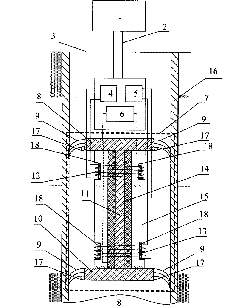
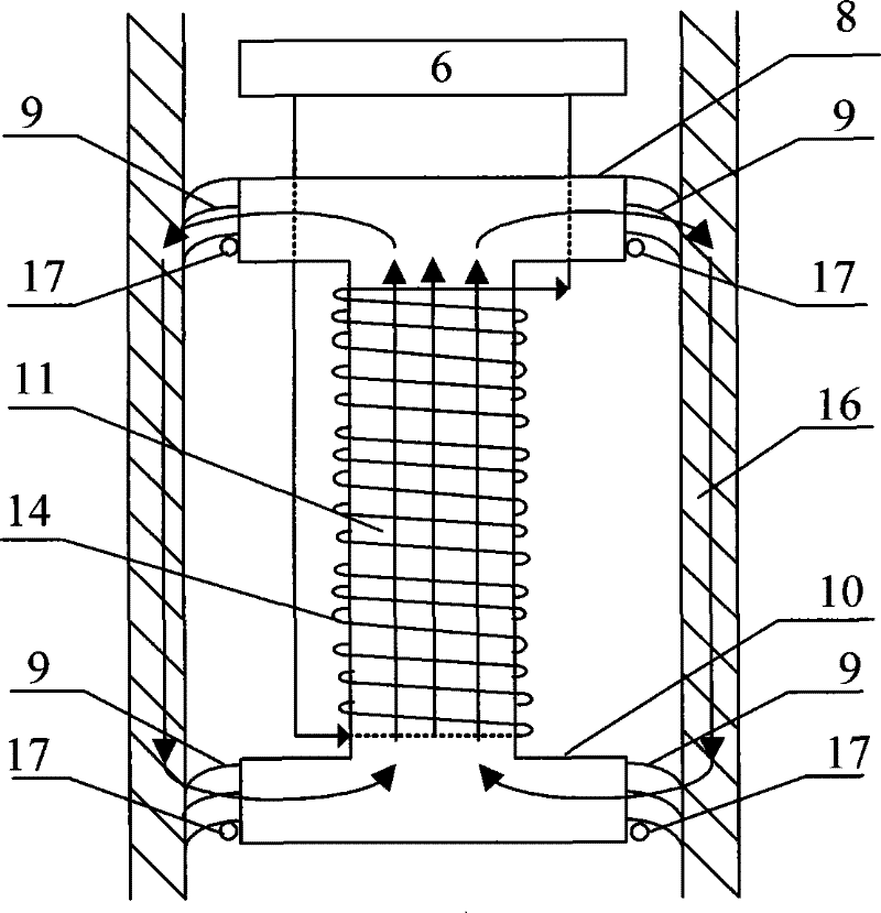
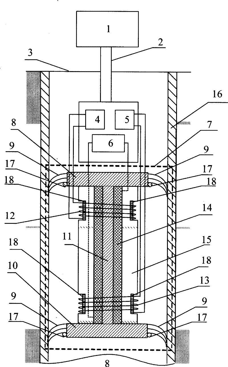
[0015] Reference figure 1 , Transient electromagnetic logging device in cased hole, including ground monitoring equipment 1, ground monitoring equipment 1 is connected to downhole logging tool 3 through cable 2, downhole logging tool 3 includes transmitting control unit 4, receiving control unit 5, magnetization The power supply 6, the magnetization device 7, the transmitting coil 12 and the receiving coil 13, the transmitting control unit 4 and the transmitting coil 12 are connected through a signal line, the receiving control unit 5 and the receiving coil 13 are connected through a data line, the magnetizing power supply 6 and the magnetizing device 7 The coils 14 are connected. The magnetized coil 14 is wrapped with a cylindrical non-metallic insulating material 15, and the insulating material 15 is provided with coil ...


PUM


Abstract

The invention discloses a transient electromagnetic logging device in a through-casing well, which comprises ground monitoring equipment (1), wherein the ground monitoring equipment (1) is connected with a downhole logging instrument (3) through a cable (2), and the downhole logging instrument (3) consists of a transmitting control unit (4), a receiving control unit (5), a magnetized power supply (6), a magnetizer (7), a transmitting coil (12) and a receiving coil (13). The device utilizes transient electromagnetic technology to transmit low-frequency high-power electromagnetic signals; according to Faraday law of electromagnetic induction, a variable magnetic field produces a variable electric field; the characteristics of an electromagnetic field are determined by the characteristics of medium; and the magnetic field which embodies the characteristics of the detected medium is received by the downhole logging instrument (3), so that the aim of identifying stratum characteristics through the signals detected by the receiving coil is achieved. The device has the characteristics of high efficiency, quickness and non-contact.

Description

Technical field [0001] The invention belongs to a logging device in the field of resource and environmental development, and particularly relates to a transient electromagnetic logging device in a through-casing well that uses a combination of casing magnetization technology and transient electromagnetic technology to realize formation detection of production wells. Background technique [0002] With the continuous progress of the oil and gas production process, a large number of production wells have entered the middle and late stages, the water cut continues to rise, and the output gradually declines. In order to increase the productivity of the oilfield, extend the life of the oilfield, and increase the recoverable reserves, it is necessary to determine the death rate in the development of the oilfield. In oil and gas zones, tracking changes in reservoir fluid saturation and the movement of reservoir liquid interfaces, while tracking changes in fluid saturation in old reservoir...

Claims


Application Information

Patent Timeline
Patent Type & Authority Patents(China)
IPC IPC(8): E21B49/00E21B47/13E21B47/00
Inventor 党瑞荣任志平宋汐瑾唐俊
Owner XI'AN PETROLEUM UNIVERSITY
Why Eureka
Try Eureka