Intelligent wind wheel used for vertical axis wind generating device

A wind power generation device, vertical axis technology, applied in the direction of wind power generator components, wind power engine control, wind power generation, etc., can solve the problems of low efficiency, large aerodynamic noise, difficult maintenance, etc., to achieve cost reduction, low aerodynamic noise, The effect of easy maintenance

Inactive Publication Date: 2009-11-18
肖玄同
View PDF0 Cites 12 Cited by
  • Summary
  • Abstract
  • Description
  • Claims
  • Application Information

AI Technical Summary

Problems solved by technology

The system is expensive and difficult to maintain
[0007] 3. The tip speed ratio of the horizontal axis wind rotor is generally around 5~7. At such a high speed, the cutting airflow of the blade will produce a lot of aerodynamic noise. At the same time, many birds ar...

Method used


Image

  • Intelligent wind wheel used for vertical axis wind generating device
  • Intelligent wind wheel used for vertical axis wind generating device

Examples


Embodiment 1

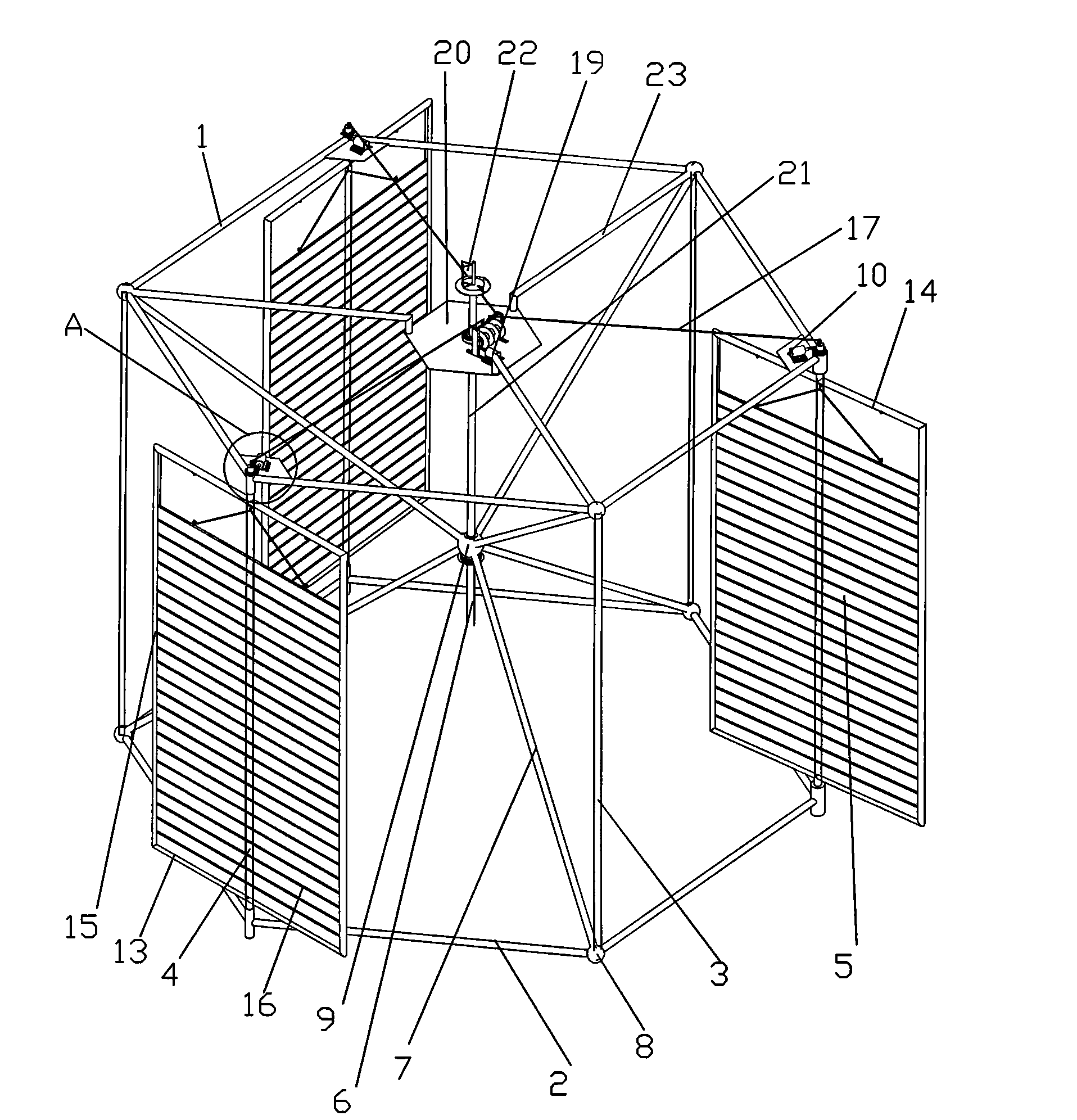
[0024] Such as figure 1 As shown, the present invention is an intelligent wind rotor for a vertical axis wind power generation device, comprising an upper rim 1 and a lower rim 2, three support rods 3 and three blade shafts 4 are arranged between the rims, and the blade shafts 4 is provided with 3 sails 5, and the wheel rim, support rod 3 and blade shaft 4 form a positive prism, and the middle part of the positive prism is provided with a wheel shaft 6, and a wheel hub 7 is arranged between the wheel shaft 6 and the wheel rim, and the upper and lower wheel rims 1 and 2 are regular polygons with 6 sides, the vertices of two adjacent sides are provided with connectors 8, and the support rods 3 and blade shafts 4 are arranged in the connectors 8 corresponding to the vertices of the upper and lower rims 1 and 2, The top of the wheel shaft 6 is provided with a fixed body 9, and the hub 7 is arranged between the fixed body 9 and the connecting body 8; the support rod 3 and the blade...

Embodiment 2

[0028] In Embodiment 1, a middle rim is provided between the upper rim and the lower rim, and the three rims are regular polygons with 8 sides, and 4 support rods and 4 blade shafts are arranged between the rims, and the blade shafts There are 4 pairs of sails on the upper rim, a hub is arranged between the connecting body connecting the blade shaft and the fixed body on the middle rim, and a hub is arranged between the connecting body connecting the support rod on the upper and lower rims and the fixed body. The sail ropes of 4 pairs of sails are respectively connected with 4 motors. Each motor is located on the hub of the middle rim, the fixed body is provided with a rod 21, and the top of the rod 21 is provided with a wind direction indicator 22, and the others are the same as in Embodiment 1.

Embodiment 3

[0030] The rim in Embodiment 1 is a regular 12-gon, and 6 support rods 3 and 6 blade shafts 4 are arranged between the rims, and each blade shaft 4 is provided with a sail 5, and the others are the same as in Embodiment 1. .

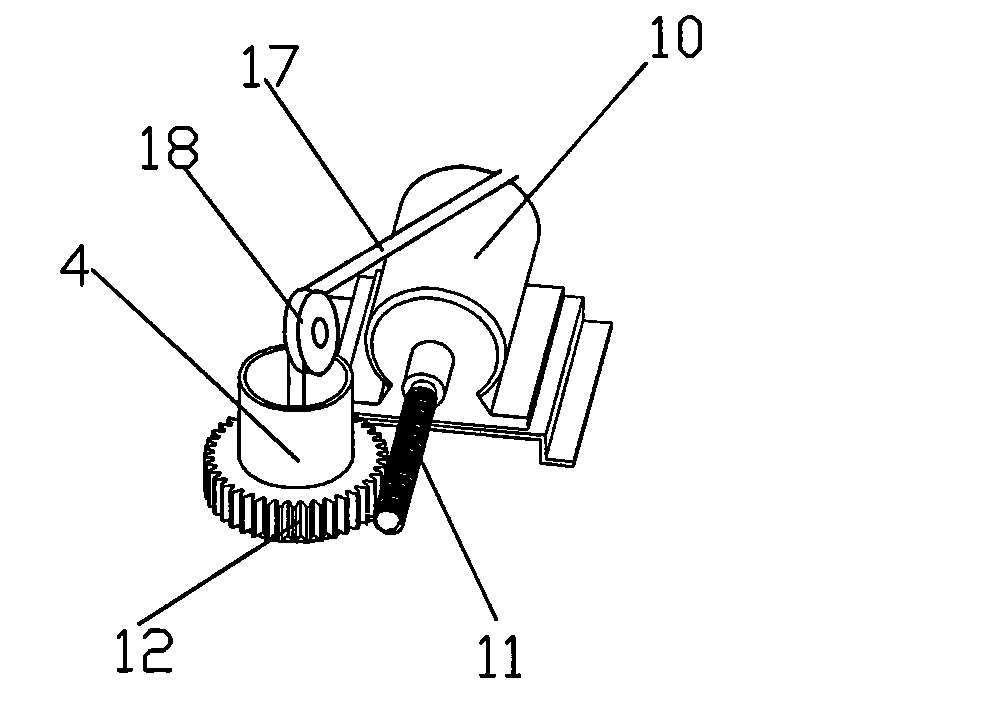
[0031] Working principle of the present invention: the canvas of the present invention can be lifted and lowered according to the size of the wind, and the blade shaft can be adjusted according to the wind direction at any time. The angle adjustment motor can adjust the angle of the blade shaft according to the instruction of the sail controller, and the The code transmits the angle of the blade shaft through the code reader to the sail controller to calculate the angle that should be adjusted.


PUM


Abstract

The invention relates to an intelligent wind wheel, in particular to an intelligent wind wheel used for a vertical axis wind generating device. The intelligent wind wheel used for the vertical axis wind generating device comprises an upper wheel rim and a lower wheel rim; a support bar and a vane shaft are arranged between the wheel rims; the vane shaft is provided with a wind sail; the wheel rims, the support bar and the vane shaft form a regular prism; the middle part of the regular prism is provided with a wheel shaft; and a wheel hub is arranged between the wheel shaft and the wheel rim. The intelligent wind wheel used for the vertical axis wind generating device has the advantages and effects that the wind wheel does not need a windward adjusting system and can receive wind from any direction in an orientation of 360 degrees, and a main shaft permanently rotates towards the design direction. The wind sail rotates along a self shaft, and continually changes direction so that the tangential stress of the wind sail is maximized down the wind and the wind sail against the wind is parallel to the wind direction. The rotating angle of the wind sail is judged by a main controller according to the indication of a wind indicator and the current rotating relative position of the wind sail, and information is transmitted to a wind sail controller. The intelligent wind wheel used for the vertical axis wind generating device can reduce the cost, is convenient to maintain, and has low pneumatic noise.

Description

technical field [0001] The invention relates to an intelligent wind wheel, in particular to an intelligent wind wheel used for a vertical axis wind power generation device. Background technique [0002] Stable, reliable and clean energy supply is the guarantee of human civilization, economic development and social progress. Fossil energy such as coal, oil, and natural gas supported the progress and development of human civilization for nearly 200 years in the 19th and 20th centuries. However, the massive consumption of fossil fuels not only makes human beings face the pressure of resource depletion, but also feels the threat of environmental degradation. The 21st century is a century of rapid development of science and technology, economy and society. It will also be a century of transition from the era of fossil fuels to the era of renewable energy with sustainable utilization capabilities, and gradually create a new era of energy for human beings to get rid of the shackle...

Claims


Application Information

Patent Timeline
IPC IPC(8): F03D3/06F03D9/00F03D11/00F03D7/06F03D13/20
CPCY02E10/72Y02E10/74
Inventor 肖玄同崔丽菊
Owner 肖玄同
Why Eureka
Try Eureka