CAN bus physical layer structure based on 1XN passive optical splitter (POS)

A CAN bus and splitter technology, applied in the field of CAN bus physical layer structure, to achieve the best anti-electromagnetic interference characteristics, increase the maximum transmission rate, and achieve the effects of wide network geographical distribution

Inactive Publication Date: 2009-11-18
蒋涵民
View PDF2 Cites 16 Cited by
  • Summary
  • Abstract
  • Description
  • Claims
  • Application Information

AI Technical Summary

Problems solved by technology

[0005] Aiming at the problems existing in the background technology, the present invention introduces the concept of optical fiber transmission point-to-multipoint into the o

Method used


Image

  • CAN bus physical layer structure based on 1XN passive optical splitter (POS)
  • CAN bus physical layer structure based on 1XN passive optical splitter (POS)
  • CAN bus physical layer structure based on 1XN passive optical splitter (POS)

Examples


Embodiment 1

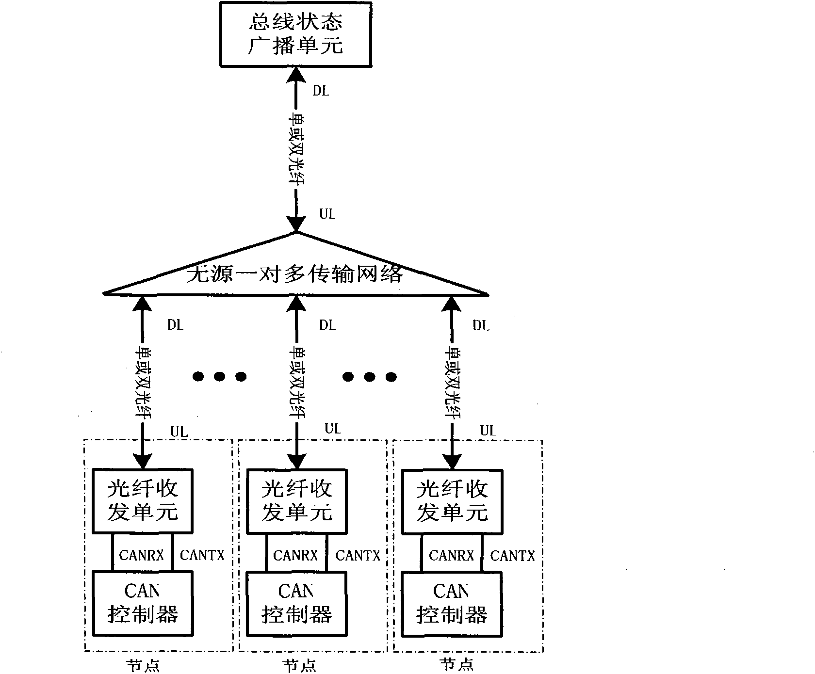
[0029] Embodiment 1: as figure 2As shown, the CAN bus physical layer structure based on 1×N passive optical splitter of the present invention is successively a bus state broadcast unit, a passive one-to-many transmission network, and some CAN nodes from top to bottom. Connections can be made using single or dual fibers. The function of the bus status broadcasting unit is to obtain the bus status belonging to all CAN nodes, and then send the bus status of the CAN nodes to all CAN nodes. The DL port of the bus broadcasting unit is connected to the UL port of the one-to-many transmission network. The bus broadcasting unit receives the uplink optical signal from the DL port, copies it into a downlink optical signal, and then transmits it downward through the DL port. Its reproduction method can be active or passive. The specific connection method is as follows: the downlink optical port DL (DOWN LINK) of the bus state broadcast unit is connected to the uplink optical port UL (U...

Embodiment 2

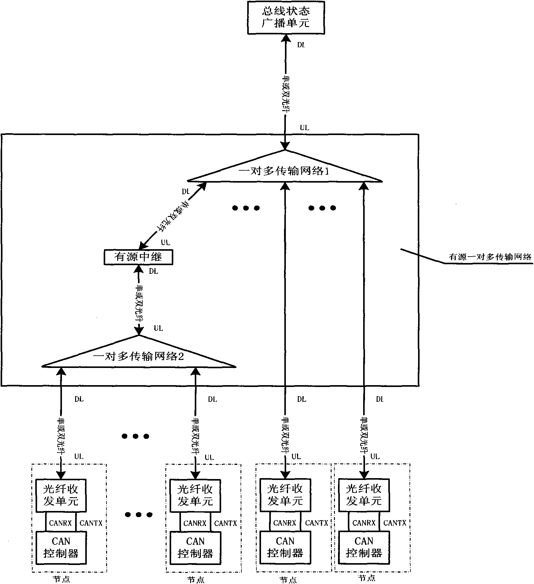
[0033] Embodiment 2: When the passive one-to-many transmission network cannot handle the scale or distance of CAN nodes, an active relay can be introduced. Such as image 3 As shown, the CAN bus physical layer structure based on 1×N passive optical splitter of another embodiment of the present invention is the bus state broadcast unit, one-to-many transmission network 1, active relay, one-to-one Multi-transport network 2 as well as some CAN nodes. Other structures are the same as those described in Embodiment 1, except that there are more active relays between two one-to-many transmission networks. Such as image 3 As shown, the active relay is between the one-to-many transport network 1 and the one-to-many transport network 2 . That is, between the downlink optical port DL of the one-to-many transmission network 1 and the uplink optical port UL of the one-to-many transmission network 2 . And the one-to-many transmission network may be an active one-to-many transmission ne...


PUM


Abstract

The invention discloses a CAN bus physical layer structure based on a 1XN passive optical splitter (POS), comprising a bus state broadcasting unit, a pair of multi-transport networks and a plurality of CAN nodes, which are sequentially connected by optical fibers; the bus state broadcasting unit comprises a lower connective light port and is used for reproducing uplink signals in the CAN bus into downlink signals; a pair of multi-transport networks comprise single or cascaded 1XN POS and are used for transporting the uplink signals and downlink signals; the CAN node comprises a CAN controller and an optical fiber transceiving unit. The CAN bus physical layer structure has excellent anti-electromagnetic interference characteristic and wider network area distribution, and simultaneously improves transmission rate greatly.

Description

technical field [0001] The invention belongs to the communication field, and in particular relates to a CAN bus physical layer structure based on a passive optical fiber network, which can be widely used in the interconnection of electronic equipment in automobiles, interconnection of household appliances, industrial field control and remote industrial equipment interconnection. Background technique [0002] CAN bus is a mature industrial bus widely used in industrial control and automotive electronics. In the CAN bus specification, only the object layer and the transfer layer are defined. The widely used physical layer structure is metal twisted pair, such as figure 1 shown. Multiple nodes are connected to the CAN bus, and each node includes a CAN controller and a driver chip. The CAN controller can be a separate control chip controlled by an external MCU, or it can itself be an MCU containing CAN controller logic. The role of the driver chip is to switch between the lo...

Claims


Application Information

Patent Timeline
IPC IPC(8): H04B10/20H04B10/12H04B10/278
Inventor 蒋涵民
Owner 蒋涵民
Why Eureka
Try Eureka