
Method and device for time template measurement

A measurement method and technology of measurement device, applied in transmission monitoring, electrical components, wireless communication, etc., can solve problems such as failure to meet measurement specification requirements

Active Publication Date: 2013-10-09
DATANG MOBILE COMM EQUIP CO LTD
View PDF3 Cites 0 Cited by
  • Summary
  • Abstract
  • Description
  • Claims
  • Application Information

AI Technical Summary

Problems solved by technology

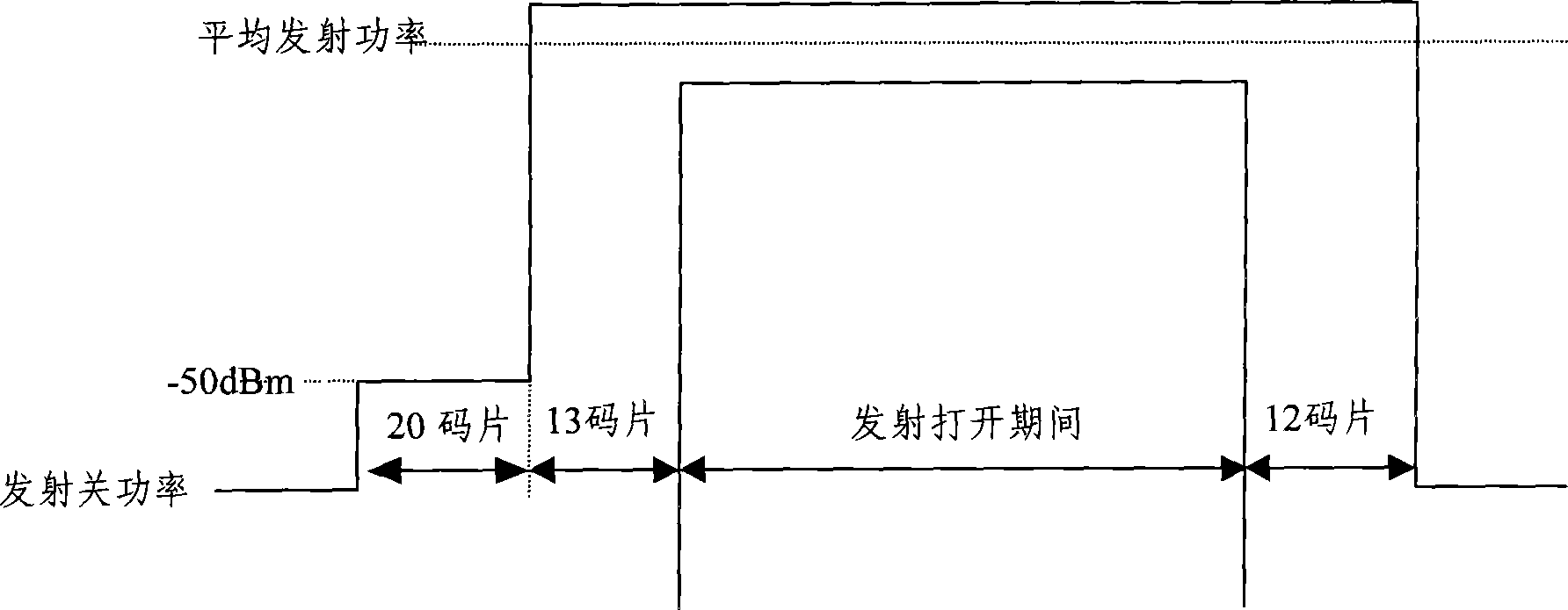
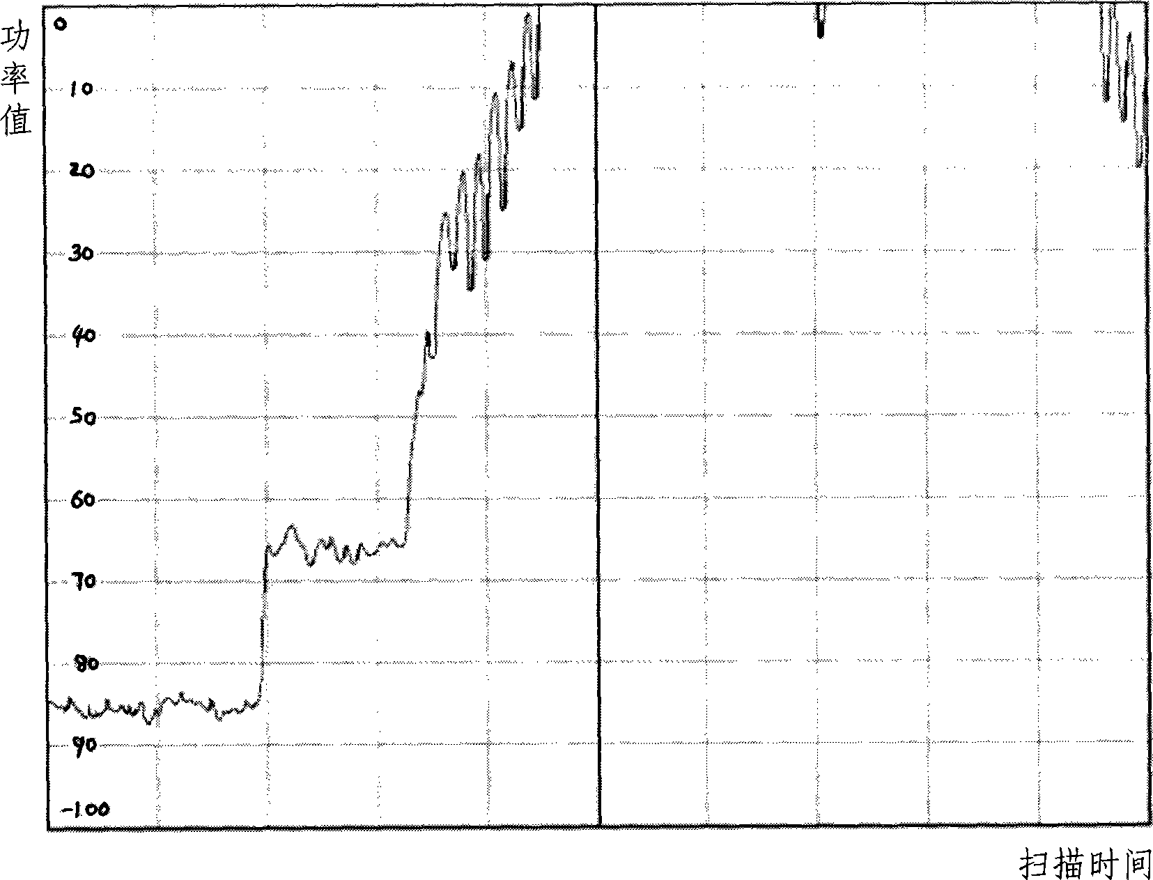
[0006] It can be seen that the current commonly used measurement methods can meet the measurement requirements of the emission time template, but because the corresponding measurement method does not pass the measured signal through the RRC filter, it cannot meet the requirements of the RRC on each chip during the transmitter off period. Measurement Specification Requirements for Filtered Average Power
That is to say, the existing measurement implementation schemes cannot simultaneously make the measurement of the emission time template and the measurement of the emission off-power meet the requirements of their respective specifications

Method used


Image

  • Method and device for time template measurement
  • Method and device for time template measurement
  • Method and device for time template measurement

Examples


Embodiment Construction

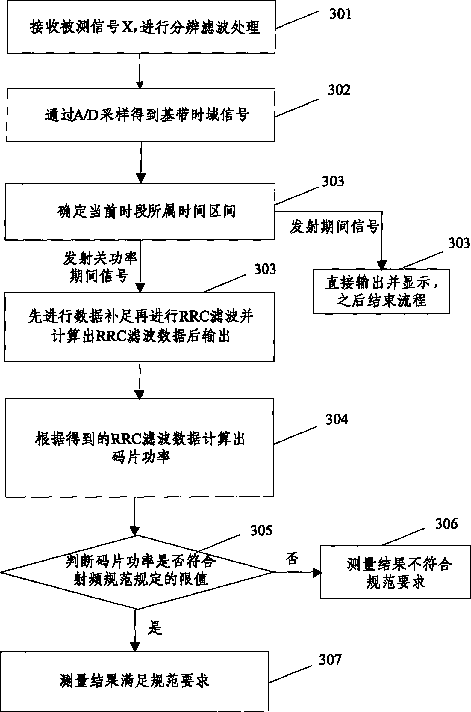
[0025] The basic idea of ​​the present invention is as follows: measure the transmit off power and the power during the transmit period in sections, directly output and display the sampled data during the transmit period specified in the transmit time template, and directly output and display the sampled data during the transmit off power period specified in the transmit time template After complementing the data and performing RRC filtering, it is output and displayed.

[0026] Further, in the measurement process, it is judged whether the chip power during the transmission off-power period conforms to the transmit off-power limit specified by the radio frequency specification, so as to ensure that the measurement result meets the requirements of the radio frequency specification.

[0027] image 3 It is a schematic flow chart of realizing the time template measurement method in the present invention, such as image 3 As shown, the method includes the following steps:

[002...


PUM


Abstract

The invention discloses a method for time template measurement, which comprises the following steps: according to the current time interval, directly outputting sampling data in transmitting period without passing through a root-raised cosine (RRC) filter; complementing sampling data during transmit-off power; and outputting the sampling data by the RRC filter. The invention also discloses a device for time template measurement, which comprises a resolution filter, an A / D sampling module and an RRS filter; the key is that the device also comprises a signal distinguishing and processing module; and the RRS filter further comprises a data complement module and an RRC filter module. The method and the device not only make the measurement for a transmitting time template accord with the code requirement, but also cannot influence the measurement of the transmit-off power.

Description

technical field [0001] The invention relates to a template measurement technology in a Time Division-Synchronous Code Division Multiple Access (TD-SCDMA, Time Division-Synchronous Code Division Multiple Access) system, in particular to a time template measurement method and device in a time division duplex mobile communication system. Background technique [0002] In the third generation (3G) mobile communication system, TD-SCDMA, one of the air interface technical specifications, is the only standard that adopts the time division duplex (TDD) mode among the three international standards of the 3G system. For the TDD system, the same frequency is used for reception and transmission, and the time-sharing is performed. In order to protect the transceiver conversion and not affect the communication system, it is generally required that the transmit power should not be turned on too early, and the tail should not be too long when the transmit power is turned off, otherwise it wi...

Claims


Application Information

Patent Timeline
Patent Type & Authority Patents(China)
IPC IPC(8): H04B17/00H04W24/00H04B17/10
Inventor 蒋守宁李凤宋月霞
Owner DATANG MOBILE COMM EQUIP CO LTD
Learn More