Transmission system of user data under SDI audio and video transmission mode and method therefor

A technology of user data and transmission mode, which is applied in the direction of pulse modulation TV signal transmission, TV, electrical components, etc., can solve the problems of complicated cable connection and many types of interfaces, and achieve the effect of simplifying engineering installation and improving system reliability

Inactive Publication Date: 2009-11-18
ZHEJIANG DAHUA TECH CO LTD
View PDF0 Cites 7 Cited by
  • Summary
  • Abstract
  • Description
  • Claims
  • Application Information

AI Technical Summary

Problems solved by technology

[0003] In order to solve the technical problems of many types of interfaces between the receiving end and the sending end and complicated

Method used


Image

  • Transmission system of user data under SDI audio and video transmission mode and method therefor
  • Transmission system of user data under SDI audio and video transmission mode and method therefor
  • Transmission system of user data under SDI audio and video transmission mode and method therefor

Examples


Embodiment 1

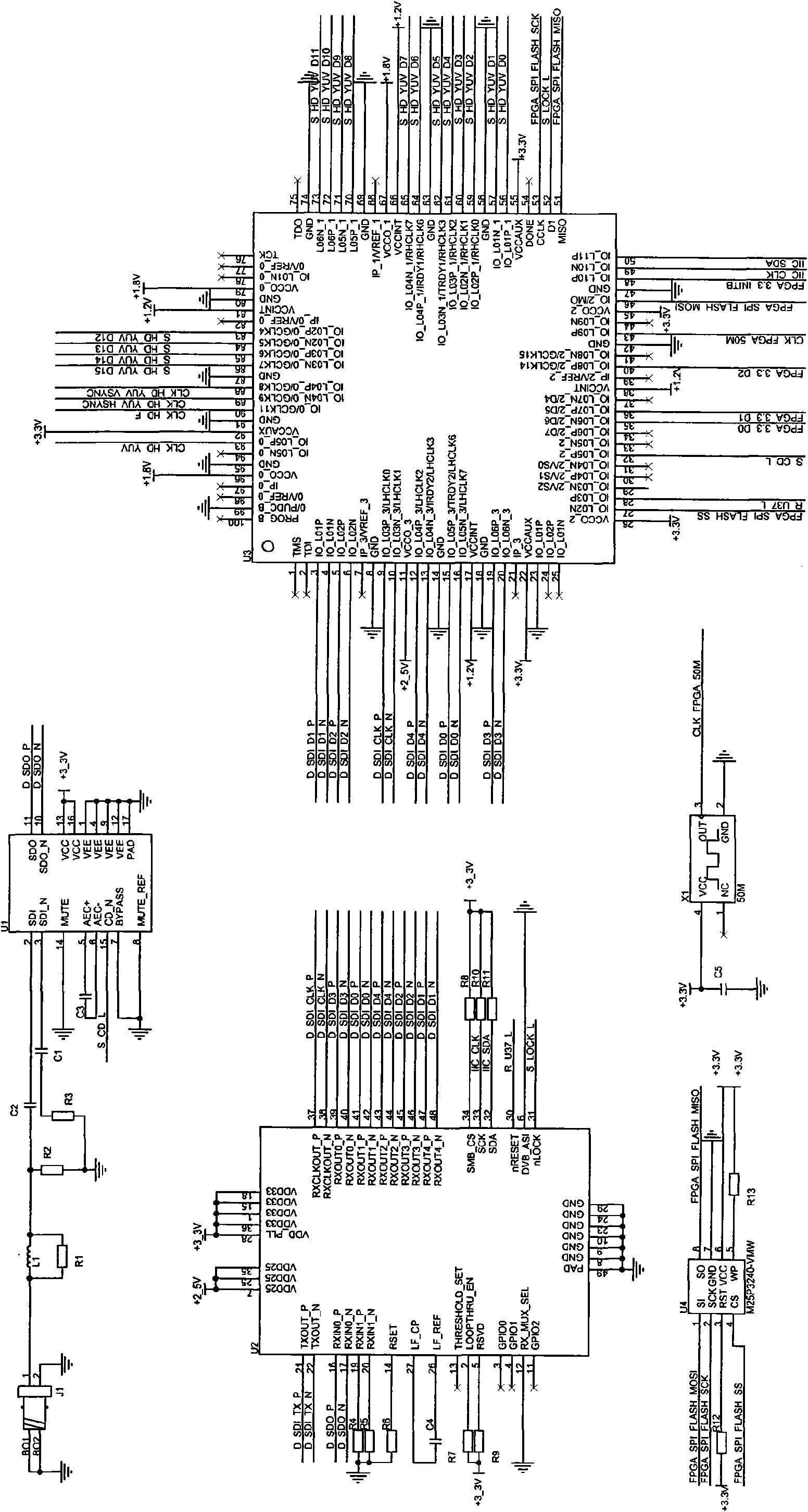
[0028] Embodiment 1: Receiver circuit of user data transmission system in SDI audio and video transmission mode

[0029] image 3Shown is the circuit diagram of the receiving end of the user data transmission system under the SDI audio and video transmission mode of the present invention. The receiving end circuit part of the present invention involves electronic components: 13 resistors R1-R13, 5 capacitors C1-C5, 1 Inductor L1, 1 connector J1, 4 integrated circuits U1-U4, 1 crystal oscillator X1. The circuit is composed of: pin 1 of the connector J1 is connected to the inductor L1 and the resistor R1, the other pins of the connector J1 are grounded, the inductor L1 and the resistor R1 are connected in parallel and then connected to the resistor R2 and the capacitor C2, the other end of the resistor R2 is grounded, and the other end of the capacitor C2 Connect to pin 2 of integrated circuit U1, pin 3 of integrated circuit U1 connect to capacitor C1, capacitor C1 and resistor...

Embodiment 2

[0032] Embodiment 2: The sending end circuit of the user data transmission system in the SDI audio and video transmission mode

[0033] Figure 4 Shown is the sending end circuit diagram of the user data transmission system under the SDI audio and video transmission mode. The sending end circuit part of the present invention involves electronic components: 11 resistors R15-R25, 4 capacitors C6-C9, and 1 inductor L2 , 1 connector J2, 3 integrated circuits U5-U7, 1 crystal oscillator X2. The circuit is composed of: pin 1 of connector J2 is connected to capacitor C9, the other pins of connector J1 are grounded, capacitor C9 is connected to inductor L2 and resistor R24, inductor L2 and resistor R24 ​​are connected in parallel to pin 16 of integrated circuit U5, integrated circuit The 16-pin series resistor R25 of U5 is connected to the power supply +2.5V, the 17-pin of the integrated circuit U5 is connected to the capacitor C8 and the resistor R23, the capacitor C8 is connected i...


PUM


Abstract

The invention discloses a transmission system of user data under an SDI audio and video transmission mode and a method therefor; the system consists of a sending terminal and a receiving terminal, wherein, the sending terminal packets the user data, edits SDI audio and video data into the user data in a mixing way according to the characteristics of video data, and sends the data into a receiving device; the receiving terminal is used for separating audio, video and user data according to the characteristics of SDI data and the video data and making user data reconstitution according to the specified format. Therefore, the aim that the user data can be synchronously transmitted under the SDI audio and video transmission mode is achieved, and a single coaxial cable is connected with a terminal device and a front end device, thus the original multi-cable connection way can be replaced, the engineering installation is simplified, and the reliability of the system is improved.

Description

technical field [0001] The present invention relates to a data transmission technology, in particular to a transmission system and method in which video data and user-defined specific-purpose data are combined and transmitted at the sending end, and the data is separated at the receiving end under the SDI audio and video transmission mode . Background technique [0002] The SDI audio and video transmission method is currently widely used in broadcasting and television systems to transmit the original data of audio and video images. It has the characteristics of large data transmission throughput and a single coaxial cable for transmission. Applying SDI video transmission technology to the field of security monitoring can achieve the purpose of transmitting high-quality high-resolution images and audio, but due to the characteristics of the field of security monitoring, there are many user-controlled data transmission requirements between the receiving end and the sending end...

Claims


Application Information

Patent Timeline
IPC IPC(8): H04N7/52H04N7/58
Inventor 殷俊傅利泉张兴明
Owner ZHEJIANG DAHUA TECH CO LTD
Why Eureka
Try Eureka