Vehicle control system
A technology for controlling systems and vehicles, applied in transmission systems, vehicle components, multi-programming devices, etc.
- Summary
- Abstract
- Description
- Claims
- Application Information
AI Technical Summary
Problems solved by technology
Method used
Image

Examples
Embodiment 1
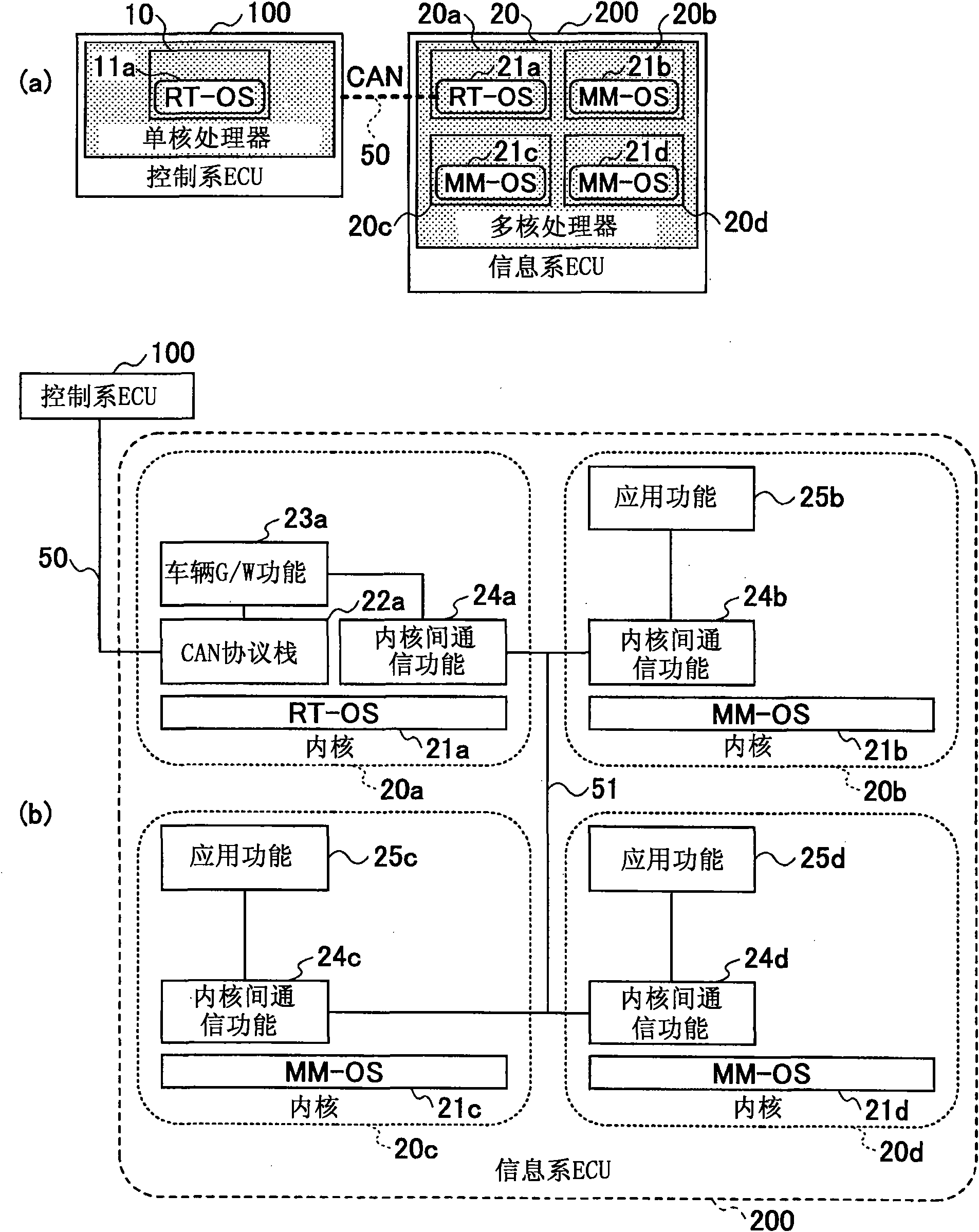
[0045] figure 1 This is the first embodiment of the vehicle control system of the present invention. The vehicle control system according to the first embodiment includes a control system ECU 100 as a control system electronic control device and an information system ECU 200 as an information system electronic control device. Both the control system ECU 100 and the information system ECU 200 are mounted on the vehicle and communicate with each other.
[0046] The control system ECU is an ECU that has a vehicle control function and controls the behavior of the vehicle such as starting / turning / stopping. Specific examples of the control system ECU include an engine ECU that controls the engine, a steering ECU that controls the steering operation, and a brake ECU that controls the braking operation. Control system ECU100 such as figure 1 As shown in (a), the processor core has a single-core processor 10 (hereinafter referred to as "core 10"), and a real-time operating system (h...
Embodiment 2
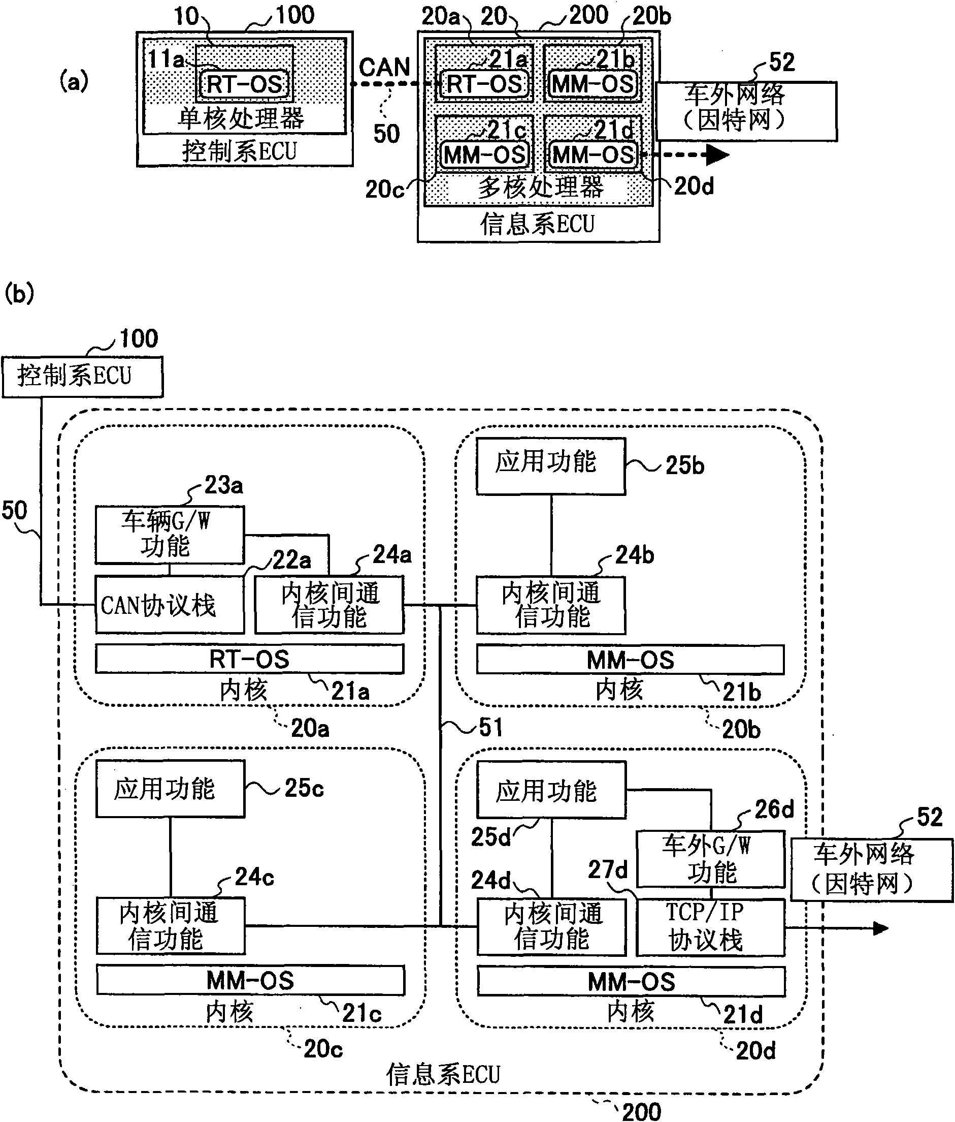
[0062] figure 2 This is the second embodiment of the vehicle control system of the present invention. The vehicle control system of the second embodiment also has a control system ECU 100 and an information system ECU 200 as in the first embodiment. Regarding the functions / configurations of the second embodiment, parts having the same functions / configurations as those of the first embodiment are denoted by the same reference numerals, and description thereof will be omitted or simplified. In the second embodiment, both control system ECU 100 and information system ECU 200 are mounted on a vehicle, and communicate with each other.
[0063] Information system ECU 200 of the second embodiment accesses a communication device outside the vehicle by connecting to communication network 52 outside the vehicle such as the Internet. Specific examples of communication devices outside the vehicle include personal computers, mobile terminals, other vehicle-mounted communication devices ...
Embodiment 3
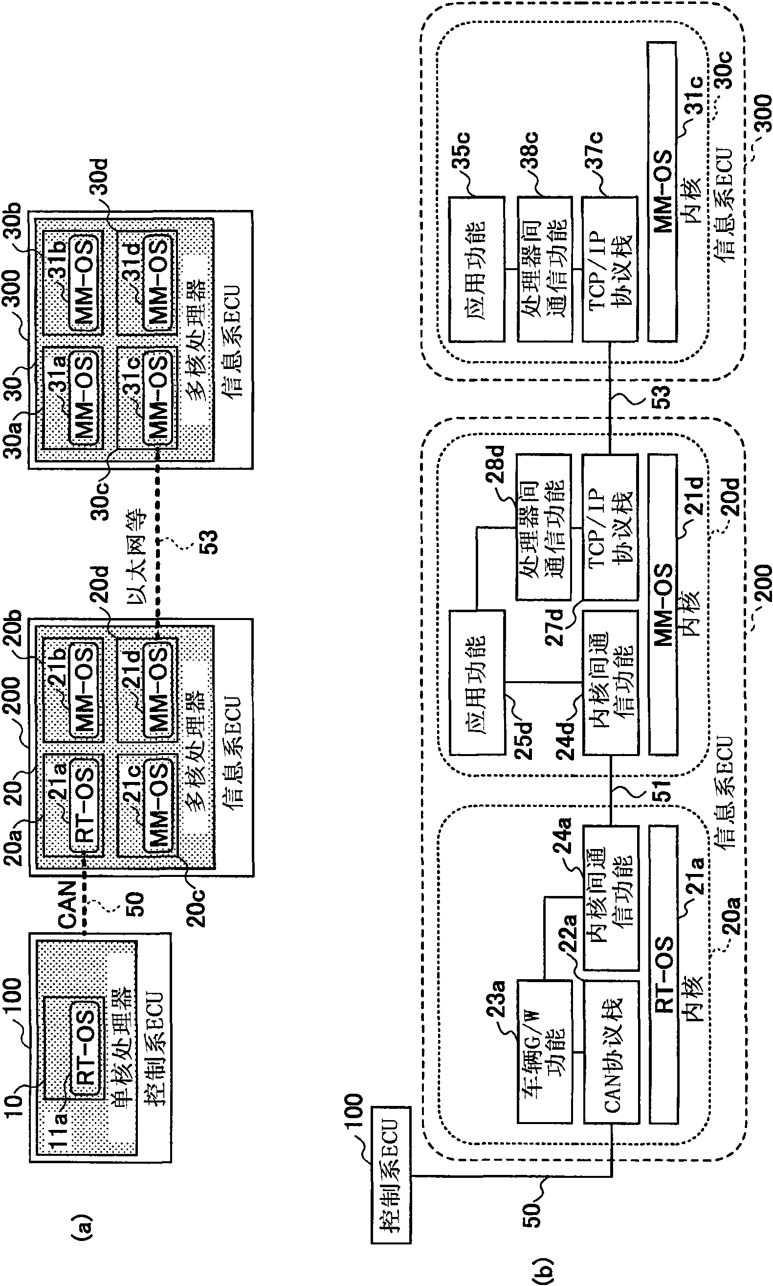
[0069] image 3 This is the third embodiment of the vehicle control system of the present invention. The vehicle control system of the third embodiment includes a control system ECU 100 , an information system ECU 200 , and an information system ECU 300 . Regarding the functions / configurations of the third embodiment, parts having the same functions / configurations as those of the first and second embodiments are denoted by the same reference numerals, and description thereof will be omitted or simplified. In the third embodiment, control ECU 100 , information system ECU 200 , and information system ECU 300 are all mounted on a vehicle. Control system ECU 100 and information system ECU 200 communicate with each other, and information system ECU 200 and information system ECU 300 communicate with each other.
[0070] image 3 Communication between information system ECU 200 and information system ECU 300 having the configuration shown in (a) is performed by kernel 20d includi...
PUM
 Abstract
Description
Claims
Application Information
 - R&D Engineer
- R&D Manager
- IP Professional
- Industry Leading Data Capabilities
- Powerful AI technology
- Patent DNA Extraction
Browse by: Latest US Patents, China's latest patents, Technical Efficacy Thesaurus, Application Domain, Technology Topic.
© 2024 PatSnap. All rights reserved.Legal|Privacy policy|Modern Slavery Act Transparency Statement|Sitemap