Femur upper segment hip-joint prosthesis

A technology of hip joint prosthesis and femur, which is applied in the field of artificial prosthesis, can solve the problem of overall aesthetics of patients without too much consideration of postoperative joint function, lack of long-term fixation and osseointegration, and failure to achieve the best use effect And other problems, to achieve the effect of long service life, reduce the frequency and probability of disease, and save medical expenses

Active Publication Date: 2009-11-25
河北春立航诺新材料科技有限公司
View PDF2 Cites 6 Cited by
  • Summary
  • Abstract
  • Description
  • Claims
  • Application Information

AI Technical Summary

Problems solved by technology

[0003] Although the above-mentioned upper femoral hip joint prosthesis can replace the patient's upper femoral hip joint, it is indeed progressive, but in actual use, it is found that there are still some shortcomings, resulting in the upper femoral hip joint prosthesis being used in practical applications. , failed to achieve the best use effect, and its shortcomings can be summarized as follows:
[0004] 1. The design of the metal circular ring is too simple, only considering the function of limb salvage, without much consideration of the postoperative joint function and the overall appearance of the patient;
[0005] 2. The fixation is not firm, and it cannot achieve long-term fixation and osseointegration, and it is only fixed by long-term scars;
[0006]3. The buttocks contracted severely after the operation, and the two buttocks were uneven in size
[0007] It can be seen that the above-mentioned existing upper femoral hip joint prosthesis obviously still has inconvenience and defects in structure and use, and needs to be further improved urgently

Method used


Image

  • Femur upper segment hip-joint prosthesis
  • Femur upper segment hip-joint prosthesis
  • Femur upper segment hip-joint prosthesis

Examples


Embodiment Construction

[0029] In order to further explain the technical means and effects that the present invention takes to achieve the intended purpose of the invention, the specific implementation, structure, characteristics and details of the upper femoral hip joint prosthesis proposed according to the present invention will be described below in conjunction with the accompanying drawings and preferred embodiments. Its effect is described in detail below.

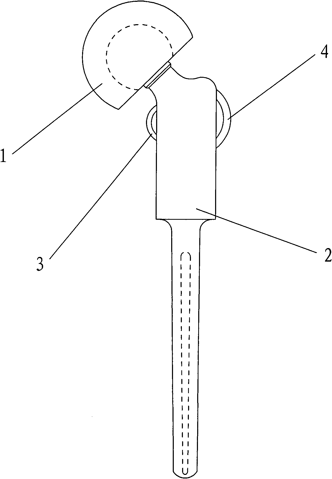
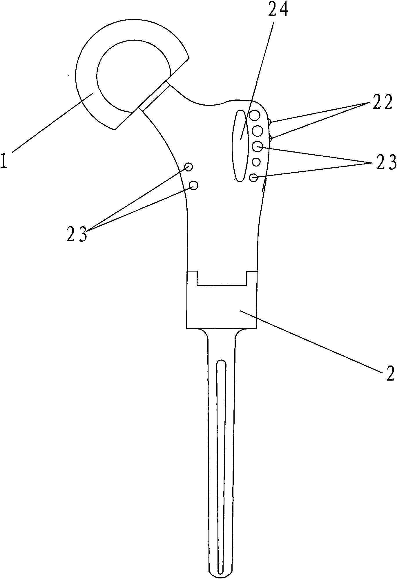
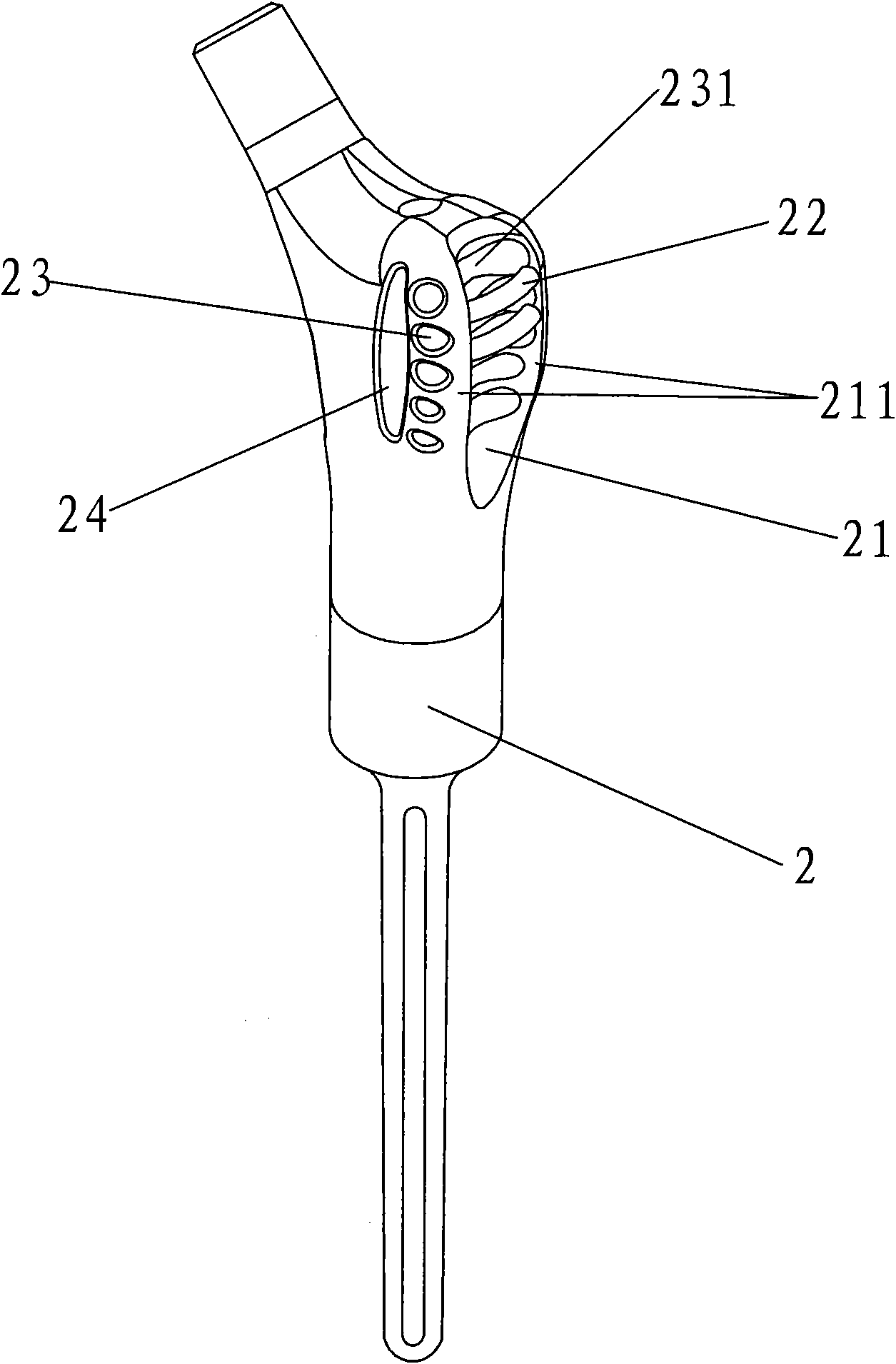
[0030] see figure 2 , image 3 As shown, the upper part of the femoral hip joint prosthesis of the present invention includes a femoral head 1 and an osteotomy segment 2, on which the osteotomy segment 2 is provided with a chute 21, a beam 22 and a suture hole 23, preferably, a bone graft Slot 24.

[0031] The chute 21 is long and deep, and is located at the back of the osteotomy 2, that is, on the side corresponding to the greater trochanter at the lower part of the human femoral neck, so that a pair of chute wings 211 are formed on the ...


PUM


Abstract

The invention relates to a femur upper segment hip-joint prosthesis composed of a femoral head (1) and an osteotomy segment (2), a sliding chute (21), crossbeams (22) and stitching holes (23) are provided on the osteotomy segment (2), wherein, the sliding chutes (21) are arranged at the back of the osteotomy segment (2) to enable the back of the osteotomy segment (2) to form a pair of sliding chute wings (211); the crossbeam is one or more than one, which are fixedly connected at outer edges of the two sliding chute wings (211); the stitching holes (23) are two or more than two, the distribution positions of which are corresponding to the large rotor and small rotor positions of the lower part of the human body femur neck. The femur upper segment hip-joint prosthesis of the invention implements the integration of the prosthesis, skelecton and muscle, the bone transplantation, the stitching and the fixing after operation are convenient, the effect after operation is good, the buttocks of the patient after operation can be more approach to original shape.

Description

technical field [0001] The invention relates to a surgically implanted artificial prosthesis, in particular to a hip joint prosthesis in the upper part of the femur. Background technique [0002] For bone defects caused by comminuted fractures, bone tumors, osteolysis and bone resorption after artificial joint surgery, amputation was often used before the 1990s. see figure 1 Shown is the upper femoral hip joint prosthesis invented and used after the 1990s, which includes a femoral head 1, an osteotomy segment 2, and two metal circular rings 3, 4, which correspond to human hip joints respectively. Two bumps on the lower part of the articular femoral neck—the lateral greater trochanter and the medial lesser trochanter. During the implementation of prosthesis replacement surgery, the two metal circular rings can play a certain connection role for the suture of muscles. [0003] Although the above-mentioned upper femoral hip joint prosthesis can replace the patient's upper fe...

Claims


Application Information

Patent Timeline
Patent Type & Authority Applications(China)
IPC IPC(8): A61F2/36
CPCA61F2/36A61F2002/30001
Inventor 史春宝刘凤鸣郑宇秋
Owner 河北春立航诺新材料科技有限公司
Why Eureka
Try Eureka