Self-powered air relief device

An unloading device and gas technology, which is applied in the direction of machines/engines, liquid variable displacement machinery, pump control, etc., can solve the problems of not being able to guarantee full sealing, large butterfly valve torque, and medium leakage, so as to improve the scope of application, reduce thickness, The effect of preventing tearing

Active Publication Date: 2009-11-25
西安志高罗茨风机技术有限责任公司
View PDF0 Cites 0 Cited by
  • Summary
  • Abstract
  • Description
  • Claims
  • Application Information

AI Technical Summary

Problems solved by technology

However, this solution requires the cooperation of electronic control, and sometimes the customer site cannot meet the requirements; moreover, the butterfly valve requires a large torque and requires external power; the butterfly valve cannot guarantee full sealing at higher temperatures, and there will be medium leakage

Method used


Image

  • Self-powered air relief device
  • Self-powered air relief device
  • Self-powered air relief device

Examples


Embodiment Construction

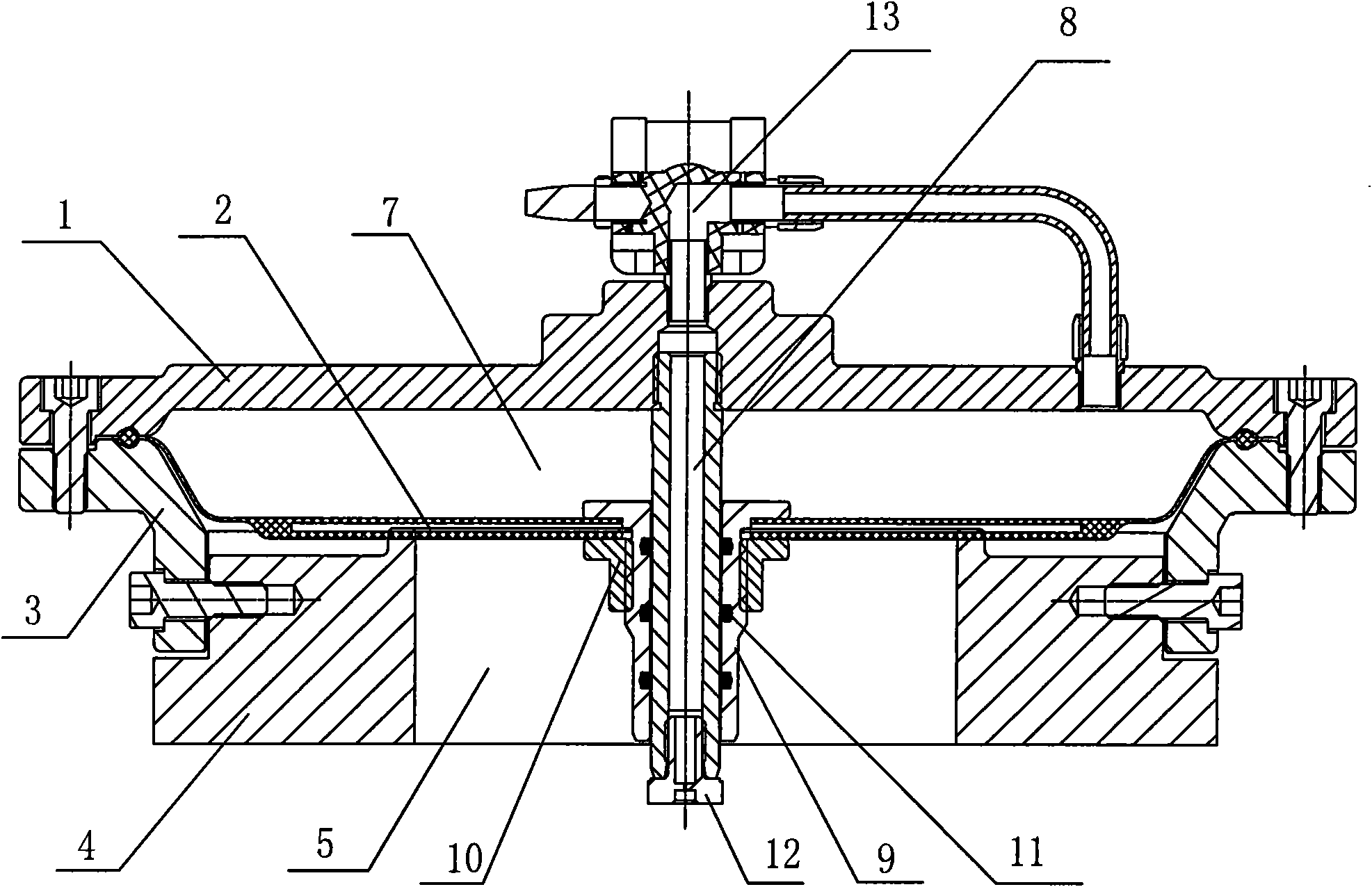
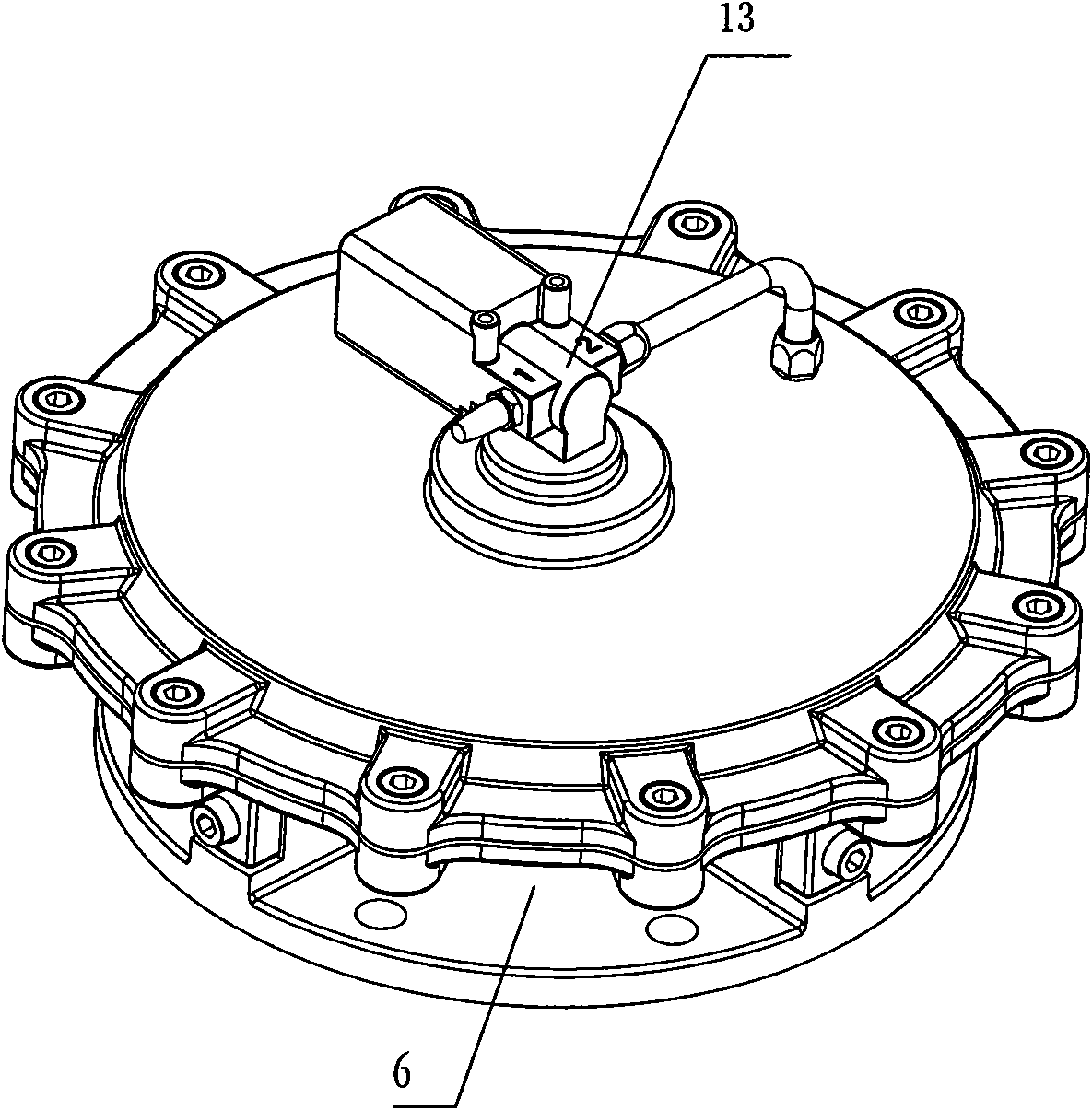
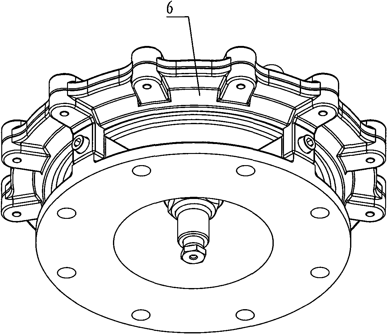
[0024] refer to figure 1 , figure 2 , image 3 , for adopting a kind of automatic power gas unloading device of the present invention, suitable for Roots blower air supply system and multi-pole centrifugal blower air supply system. Among them, the diaphragm frame 3 is evenly opened with a plurality of side air exhaust holes 6 in the circumferential direction, and the base 4 has 5 large-sized central air ducts. One end of the diaphragm frame 3 is clamped to the outlet end of the base 4 and fixed by screws; the other end of the diaphragm frame 3 is connected to the mouth of the top cover 1 by bolts, and the diaphragm 2 is fixed between the two to realize the top cover. 1. The coaxial stacking connection of the diaphragm 2, the diaphragm frame 3 and the base 4.

[0025] In the center of the diaphragm 2 , the central guide sleeve 9 is fastened on the diaphragm 2 by a fixed sleeve 10 . The center of the top cover 1 is connected with an air guide tube 8, one end of the air guid...


PUM


Abstract

The invention discloses a self-powered air relief device, which comprises a top cover (1), a membrane (2), a membrane frame (3) provided with a side wing exhaust hole (6), and a base (4) provided with a central air duct (5), wherein the top cover, the membrane, the membrane frame and the base are sequentially and coaxially overlapped; the top cover (1) and the membrane (2) form a cavity (7); the central air duct (5) is communicated with the side wing exhaust hole (6); the area of the membrane (2) is greater than the sectional area of the central air duct (5); the center of the top cover (1) is provided with an airway tube (8); one end of the airway tube (8) extends into the central air duct (5) and the other end of the airway tube (8) extends out of the top cover (1) to be connected with a reversing valve (13); one outlet of the reversing valve (13) serves as an air exhaust opening and the other outlet of the reversing valve (13) is communicated with the cavity (7); the membrane (2) is provided with a central guide sleeve (9) which is sleeved on the airway tube (8) in a sliding way; and the reversing valve (13) selectively charges air into and discharges air in the cavity (7) to drive the membrane (2) to open and close the central air duct (5) selectively.

Description

technical field [0001] The invention relates to the field of air delivery, in particular to an automatic power gas unloading device. Background technique [0002] In the field of gas transportation, unloading valves are usually used in order to realize the no-load and shock-free start-up of the fan, the uninterrupted fan switching of the system, and the recoil-free shutdown of the fan. Especially for Roots blower air supply system and multi-pole centrifugal blower air supply system with large flow rate, the unloading valve is required to open and close slowly, be controllable and allow full flow to pass through. [0003] At present, the function of unloading valve is generally realized by the cooperation of electric actuator and butterfly valve. However, this solution requires the cooperation of electronic control, and sometimes the customer site cannot meet the requirements; moreover, the butterfly valve requires a large torque and requires external power; the butterfly va...

Claims


Application Information

Patent Timeline
Patent Type & Authority Applications(China)
IPC IPC(8): F04B49/08
Inventor 刘伟石卫路前进高海
Owner 西安志高罗茨风机技术有限责任公司
Why Eureka
Try Eureka