Novel flexible thin-film battery and manufacturing method thereof

A flexible thin film and thin film battery technology, applied in primary batteries, electrodes of primary batteries, battery electrodes, etc., can solve the problems of thick thickness of flexible thin film batteries, low conductivity of current collectors, poor current collecting effect, etc., and achieve good conductivity. , high capacity, high strength effect

Inactive Publication Date: 2009-11-25
晟茂(青岛)能源替代产品研发有限公司
View PDF0 Cites 23 Cited by
  • Summary
  • Abstract
  • Description
  • Claims
  • Application Information

AI Technical Summary

Problems solved by technology

The thickness of the flexible thin film battery produced by this method is relatively thick, reaching 0.6mm to 1mm, the capacity is low, and the conductivity of the current collector is low, and the current collection effect is poor.

Method used


Image

  • Novel flexible thin-film battery and manufacturing method thereof
  • Novel flexible thin-film battery and manufacturing method thereof
  • Novel flexible thin-film battery and manufacturing method thereof

Examples


Embodiment 1

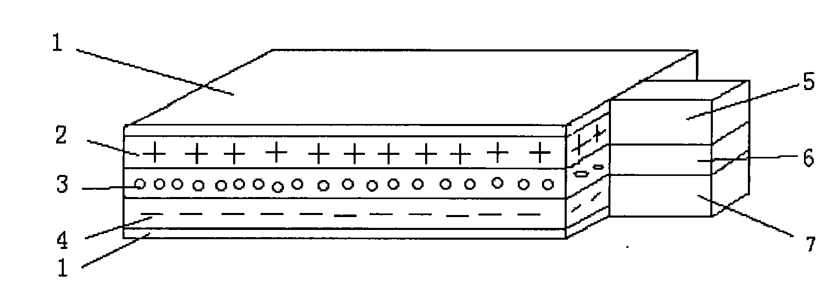
[0032] The lead wire given in this embodiment is a protruding flexible thin film battery structure. The longitudinal section is as follows: figure 1 shown. figure 2 , image 3 , Figure 4 Schematic diagrams of the structures of each part of this embodiment are given respectively.

[0033] exist figure 1 , figure 2The first example, first, with 40% NH 4 Cl solution added ZnCl 2 Prepare an electrolyte solution, and then immerse the special multifunctional polymer film in the electrolyte solution for 30 minutes to make a wet electrolyte isolation layer.

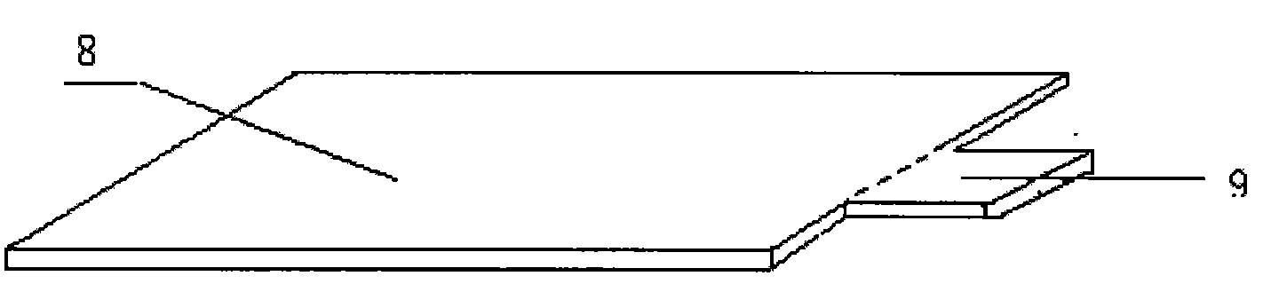
[0034] then press figure 2 Shape Cut the composite rubber conductive film with a thickness of about 0.08mm to obtain the current collector electrode film part 8 with a size of 40×50mm and the current collector lead part 9 protruding from one end of the current collector conductive film.

[0035] Plating a layer of zinc 12 on both sides of the current collector electrode film part 8 makes the thin film battery negative...

Embodiment 2

[0040] This embodiment provides a combined flexible thin film battery, the longitudinal section structure of the combined flexible thin film battery is as follows Figure 5 shown.

[0041] According to the manufacturing method of the above-mentioned embodiment 1, two groups of flexible thin-film batteries are obtained. The two batteries are directly stacked, and the lead part is made of conductive materials, so that the batteries can be connected in series or in parallel to obtain a combined flexible thin-film battery.

[0042] The combined flexible thin-film battery is externally connected to a load to test the voltage value. The test result: it drops from 3.15V to 2.3V at room temperature, and can maintain a current of 18μA / cm for 7 consecutive days. This method can form the series connection of the required multi-layer batteries, and can also realize the parallel connection of the batteries through the connection of the conductors.

[0043] It is found by the performance t...

Embodiment 3

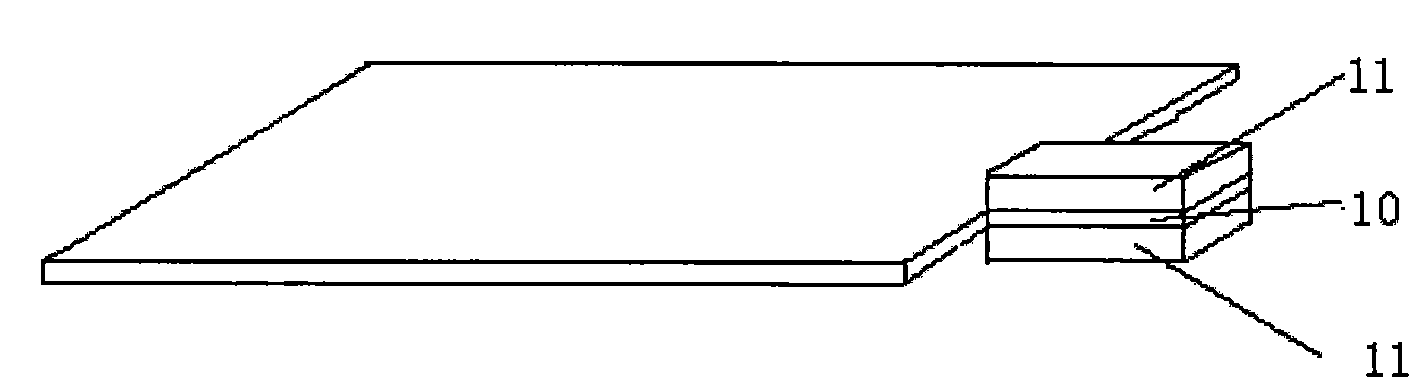
[0046] This embodiment provides a flexible film battery with leads on the edge, and its structural longitudinal section is as follows Image 6 shown.

[0047] The materials and processing methods used in the insulating layer 13, the positive electrode layer 14, the electrolyte separation layer 15, and the negative electrode layer 16 in this embodiment are the same as in the first embodiment, the main difference is that the lead part of the battery is not protruding, but is located at the edge of the battery, and the lead part It includes a positive electrode lead layer 17 , an insulating layer 18 and a negative electrode lead layer 19 . The fabrication methods of the positive electrode lead layer 17 , the insulating layer 18 and the negative electrode lead layer 19 in this embodiment are the same as those in the first embodiment. The positive electrode layer 14, the electrolyte separator layer 15, the insulating layer 18 and the negative electrode layer 16 are laminated, and ...


PUM

PropertyMeasurementUnit
thicknessaaaaaaaaaa
thicknessaaaaaaaaaa
thicknessaaaaaaaaaa

Abstract

The invention discloses a novel flexible thin-film battery and a manufacturing method thereof. The flexible thin-film battery is characterized in that the thickness of the flexible thin-film battery is less than 0.5 millimeter; and the flexible thin-film battery has high capacitance, can be freely bended and made into different shapes according to actual needs. The thin-film battery takes two special rubber composite electro-conductive film layers as a battery current collector which is divided into leads and a polar membrane, wherein anode film layers of the thin-film battery is prepared by respectively attaching cathode materials to the outer surface of one polar membrane part of the current collector; cathode film layers are prepared by attaching anode materials to the outer surface of another polar membrane part of the current collector; and a functional polymeric material having relatively strong hydroscopic property absorbs electrolyte as an electrolyte isolated layer; and then an insulating layer is added and die pressing is adopted, and the thin-film battery is obtained. The flexible thin-film battery can be overlapped by multilayer batteries to connect in series to form a power source, is widely applied in various aspects of smart cards, communication, calculators, toys, RFID (Radio Frequency Identification), labels, music greeting cards and the like.

Description

technical field [0001] The invention relates to a flexible thin film battery and a manufacturing method thereof, in particular to a disposable flexible thin film battery and a manufacturing method thereof. Background technique [0002] With the rapid development of small precision electronic products such as electronic computers, smart cards, toys, electronic watches, and temperature measurement, there is an increasing demand for small flexible thin-film batteries. At the same time, the requirements for discharge energy, thickness and flexibility of thin-film batteries Higher and higher. [0003] Generally, a laminated flexible thin film battery includes a layer of positive electrode current collector, a layer of positive electrode, a layer of electrolyte, a layer of negative electrode, a layer of negative electrode current collector and the outer shell material of the battery. The manufacturing principle of laminated thin-film batteries is simple, but the currently well-kn...

Claims


Application Information

Patent Timeline
Patent Type & Authority Applications(China)
IPC IPC(8): H01M6/00H01M2/20H01M4/64H01M4/66H01M4/06H01M4/36H01M4/62H01M2/16H01M50/417H01M50/489H01M50/526
CPCY02E60/12
Inventor 耿世达
Owner 晟茂(青岛)能源替代产品研发有限公司
Why Eureka
Try Eureka