Heavy-duty steel pile lifting clamp of cutter-suction dredge

A cutter-suction dredger and heavy-duty steel technology, which is applied in the field of heavy-duty steel pile lifting fixtures for cutter-suction dredgers, can solve problems such as insufficient friction, uneven force, wear and tear of command ropes and steel piles, and achieve The effect of increasing the contact area, reducing mutual wear, and quickly clamping the steel pile

Inactive Publication Date: 2009-12-02
SHANGHAI JIAO TONG UNIV
View PDF0 Cites 5 Cited by
  • Summary
  • Abstract
  • Description
  • Claims
  • Application Information

AI Technical Summary

Problems solved by technology

[0002] The steel piles of modern large-scale cutter suction dredgers that adopt steel pile positioning weigh more than 100 tons, and most of them are equipped with command rope lifting systems. The steel piles are all severely worn, which affects the service life of the commander rope and the steel piles; second, the friction between the commander rope and the steel piles is not suitable for control, and slippage will occur, and the operating efficiency is not high
Its disadvantages are: the contact part between the ring plate and the steel pile is a fixed clamping plate and an adjustable clamping plate, the contact surface is small and uneven, resulting in serious wear of the steel pile and the clamping plate; when the steel pile is lifted, the ring plate is tightened It is still in contact with the steel pile, which also causes the wear of the steel pile and the clamping plate; the friction force is generated by the inclination of the locking ring plate, and it is prone to slipping due to insufficient friction force

Method used


Image

  • Heavy-duty steel pile lifting clamp of cutter-suction dredge
  • Heavy-duty steel pile lifting clamp of cutter-suction dredge
  • Heavy-duty steel pile lifting clamp of cutter-suction dredge

Examples


Embodiment Construction

[0015] The embodiments of the present invention are described in detail below. This embodiment is implemented on the premise of the technical solution of the present invention, and detailed implementation methods and specific operating procedures are provided, but the protection scope of the present invention is not limited to the following implementation example.

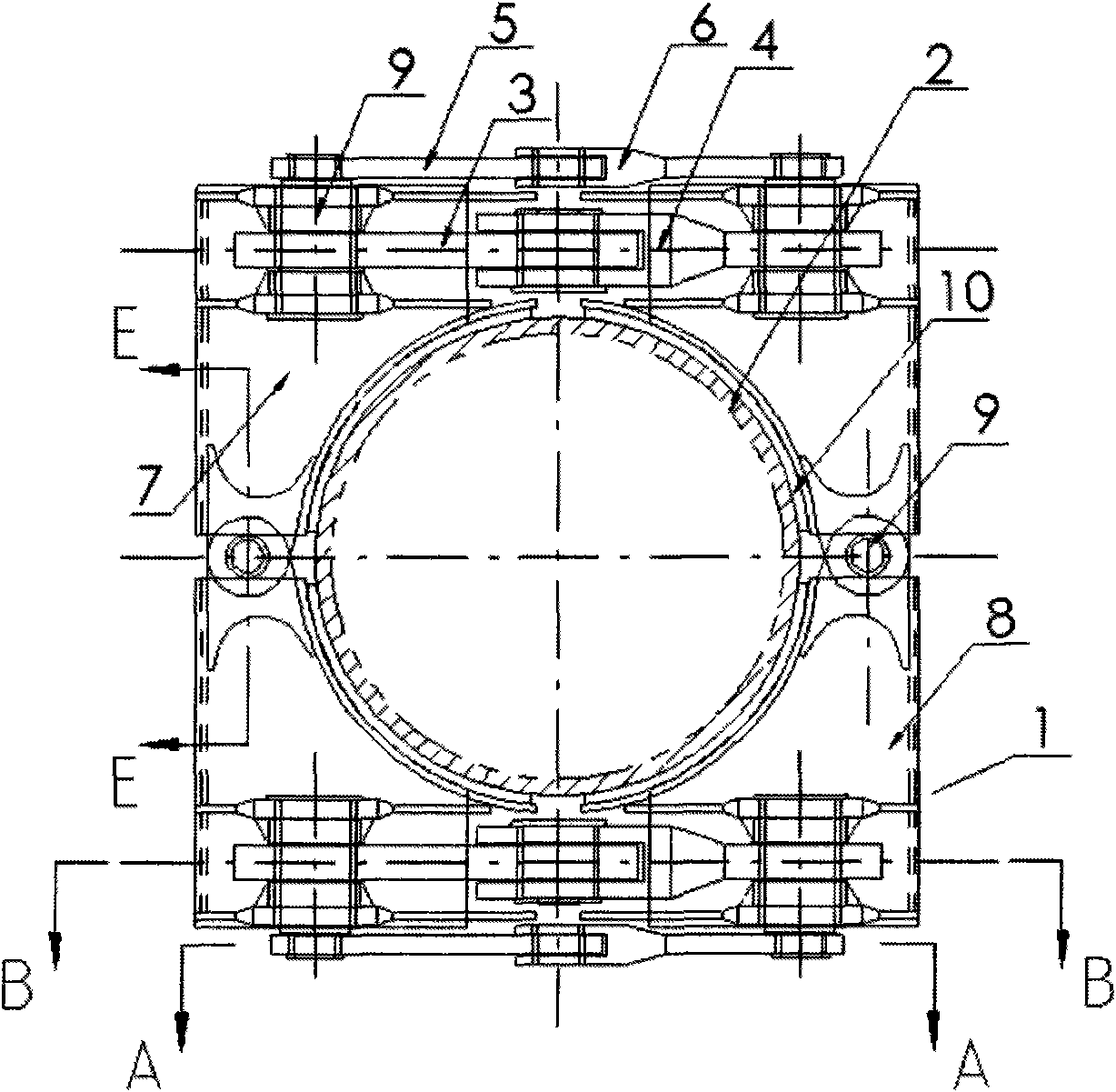
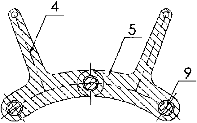
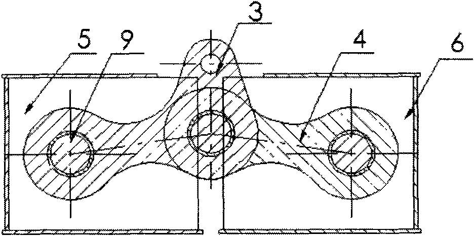
[0016] Such as figure 1 , figure 2 and image 3 As shown, this embodiment includes: two clamping assemblies 1 with symmetrical structures, the head and tail of the two clamping assemblies 1 are fixed by pin shafts and radially arranged on the outer circumference of the steel pile 2 of the dredger. The clamping assembly 1 includes: a first main lifting arm 3, a second main lifting arm 4, a first auxiliary lifting arm 5, a second auxiliary lifting arm 6, a first crank arm 7 and a second crank arm 8, wherein: the clamping The component 1 is a semicircular structure, which is connected by a connecting pin 9 to form...


PUM


Abstract

The invention discloses a heavy-duty steel pile lifting clamp of a cutter-suction dredge in the field of engineering lifting technology. The heavy-duty steel pile lifting clamp comprises two clamping components with a symmetrical structure, the heads and the tails of the two clamping components are fixed by pin shafts and radially arranged on the outside circumference of steel piles of the dredge, and the clamping components comprise a first main lifting arm, a second main lifting arm, a first auxiliary lifting arm, a second auxiliary lifting arm, a first crank arm and a second crank arm, wherein the first main lifting arm, the second main lifting arm, the first auxiliary lifting arm and the second auxiliary lifting arm are symmetrically pinned on the first crank arm and the second crank arm which are arranged oppositely respectively. While quickly generating a clamping force when the steel piles are lifted, the heavy-duty steel pile lifting clamp makes the contact forces of the clamp and the steel piles evenly distributed; and when the clamp is opened, the even opening degree is large enough, so that the lifting clamp can freely ascend and descend to avoid the friction with the steel piles.

Description

technical field [0001] The invention relates to a device in the technical field of hoisting machinery, in particular to a heavy-duty steel pile lifting fixture of a cutter suction dredger. Background technique [0002] The steel piles of modern large-scale cutter suction dredgers that adopt steel pile positioning weigh more than 100 tons, and most of them are equipped with command rope lifting systems. The steel piles are all seriously worn, which affects the service life of the commander rope and the steel piles; the second is that the friction between the commander rope and the steel piles should not be controlled, slipping will occur, and the operating efficiency is not high. Therefore, there is a need for a heavy-duty steel pile lifting fixture with uniform clamping force, sufficient friction, durability and high efficiency. [0003] After searching the literature of the prior art, it was found that Zhang Zhixue published "New Splinting Pile Lifting System—Elaboration o...

Claims


Application Information

Patent Timeline
Patent Type & Authority Applications(China)
IPC IPC(8): B66C1/48
Inventor 何炎平赵永生谭家华顾敏童
Owner SHANGHAI JIAO TONG UNIV
Why Eureka
Try Eureka