Charging nozzle of inflation pump

A pump and inflator technology, applied in vehicle maintenance, functional valve types, control valves, etc., can solve the problems of large air intake, impracticality, inability to provide air nozzles, etc., to achieve smooth air intake and small structure and volume Effect

Inactive Publication Date: 2009-12-02
黄英哲 +1
View PDF0 Cites 8 Cited by
  • Summary
  • Abstract
  • Description
  • Claims
  • Application Information

AI Technical Summary

Problems solved by technology

[0004] The aforementioned two types of screw-connected gas nozzle designs have been widely sold by the inventors in the market and have been well received. However, as various gas nozzles continue to have new market demands, some developers have developed such image 3 Another type of French air nozzle 50 is shown. The feature of this type of French air nozzle 50 is to cancel the thread of the original aforementioned first threaded part 61 and replace it with an unthreaded pipe body 51, only retaining the same as the aforementioned The second threaded portion 62 is the same as the threaded portion 52 and the air inlet 53, so as far as the existing screwed inflatable nozzle is concerned, only the aforementioned inflated nozzle 80 is available for use, but the transfer type inflated nozzle The 80 is only used to adapt the American valve 72, and it is not practical for those who specialize in the French valve 50, especially the large air intake of the French valve 50, which is widely used in racing cars. Of course, the user will choose a dedicated air nozzle to avoid unnecessary trouble and the possibility of failure during the transfer. The product obviously cannot provide an inflatable nozzle for the aforementioned situation, so it is obviously necessary to develop a structure that can be used for the aforementioned French-style gas nozzle 50 and is also a screw-in gas nozzle.

Method used


Image

  • Charging nozzle of inflation pump
  • Charging nozzle of inflation pump
  • Charging nozzle of inflation pump

Examples


Embodiment Construction

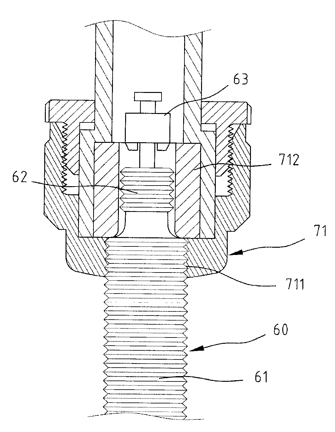
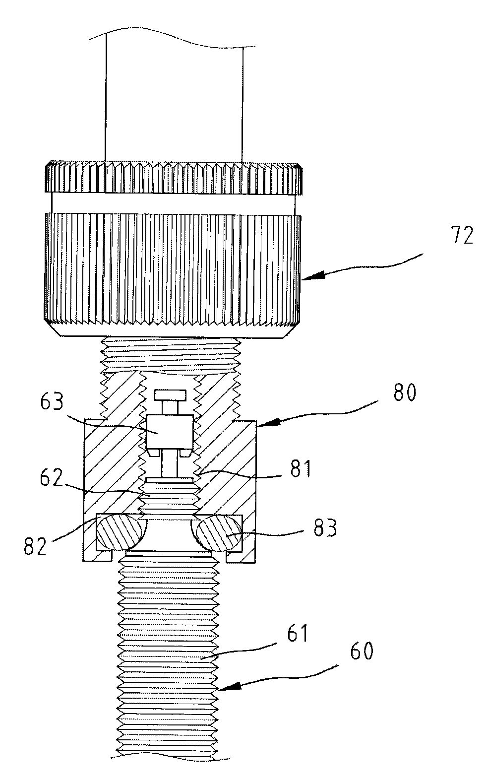
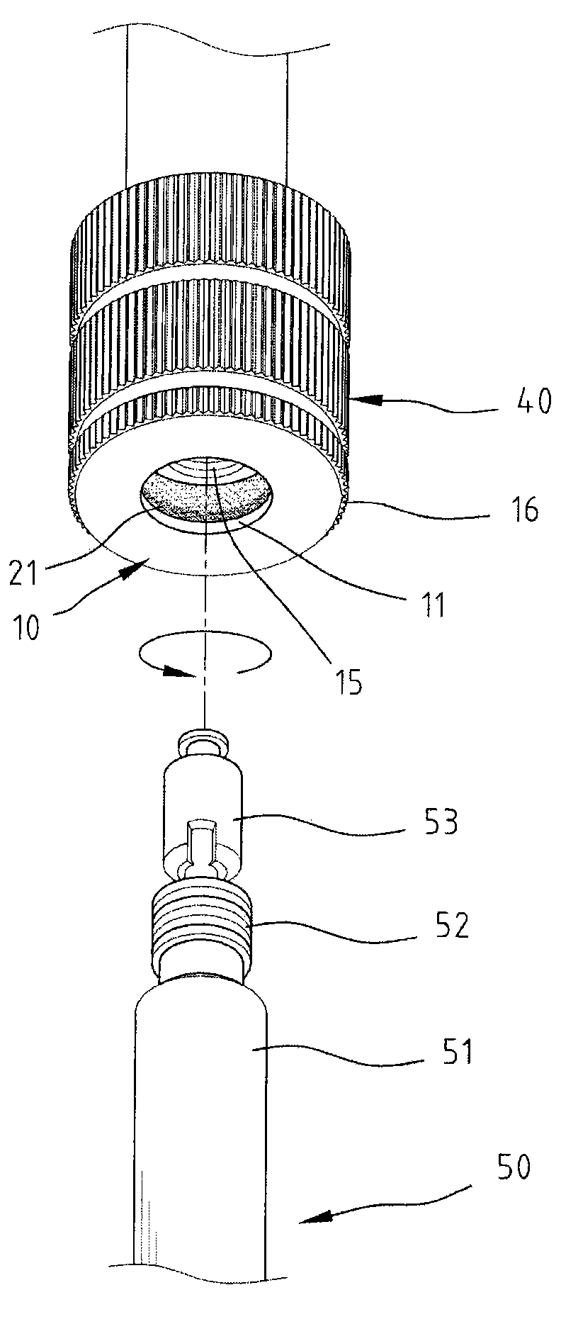
[0030] Figure 4 shows a schematic diagram of structural decomposition of the present invention and Figure 5 The disassembled sectional view, under the background of the invention of the so-called French air nozzle 50 of the present invention screwed with the inflation nozzle, the present invention is the design of the air intake end with a central pipe seat 30 connected to the inflation tube of the pump, in the central pipe seat 30 A central hole 312 is formed at the center of one end connecting the aforementioned inflatable tube, and a chamber 31 with a larger diameter than the other end of the central hole 312 is formed. 311; and the periphery of the central tube base 30 is provided with a shell 40, the shell 40 is a U-shaped body, one end of the larger opening is inserted from the central hole 312 of the central tube base 30, and the other end of the larger opening is provided with a circular diameter Smaller through hole 42, the outer edge surface of the through hole 42...


PUM


Abstract

The invention discloses a charging nozzle of an inflation pump, used on an upper threaded part of a French nozzle. The charging nozzle comprises a center pipe seat, an outer shell and a nozzle cover, wherein a center hole is arranged at one end of the center pipe and connected with a charging pipe of the inflation pump, and a cavity is arranged at the other end; the inner edge of one opening at one end of the outer shell is provided with an inner fixed part, the other end of the outer shell is provided with a through hole, and the inside diameter of the outer shell is an outer ring sleeved on the center pipe seat; the outer circular surface of the nozzle cover is provided with a first ring groove corresponding to one end of the cavity, and the first ring groove is provided with an elastic gasket; the outer circular surface of the nozzle cover is additionally provided with an outer fixed part in threaded connection with the inner fixed part so that part of the nozzle cover is arranged in the cavity; the inner circumference of the nozzle cover is provided with an inner threaded pipe for the threaded part of a tire nozzle to be threaded in, the end of the inner circumference of the nozzle cover, which corresponds to the tire nozzle, is provided with a second circular groove, and the second circular groove is provided with an elastic gasket. The charging nozzle can be taken and used randomly by a consumer with special need.

Description

technical field [0001] The invention relates to an inflator nozzle for an air pump used in a bicycle tire inflator, in particular to an inflator nozzle used in an upper screw joint of a French air nozzle. Background technique [0002] Such as figure 1 as shown, figure 1 It shows the schematic diagram of the inflatable nozzle in the prior art and the general French-style gas nozzle when it is inflated. The main feature of the appearance of the so-called French-style gas nozzle 60 is that the gas nozzle of this specification has two sections outside the nozzle, and the bottom section is a circle diameter After the first threaded part 61 which is larger and the outer ring is provided with threads and its upper end has a tapered section with a reduced diameter, there is a second threaded part with a shorter diameter and length and the outer ring is provided with threads 62, is generally widely used French-style air nozzle specifications, and has been widely used on today's whe...

Claims


Application Information

Patent Timeline
Patent Type & Authority Applications(China)
IPC IPC(8): F04B39/12F04B33/00
CPCF16K15/20B60S5/04
Inventor 黄英哲黄俊铭
Owner 黄英哲
Why Eureka
Try Eureka