Backlight source
A technology of backlight source and light source, applied in the field of backlight source, can solve the problems of reducing the utilization efficiency of light source, light loss, etc., and achieve the effects of avoiding absorption loss, improving utilization rate, and improving luminous brightness.
- Summary
- Abstract
- Description
- Claims
- Application Information
AI Technical Summary
Problems solved by technology
Method used
Image
Examples
Embodiment 1
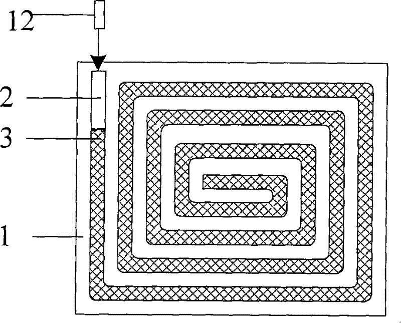
[0034] Figure 2(a) is a top view of a backlight made of side-emitting optical fibers, and Figure 2(b) is a front cross-sectional view of the substrate, image 3 It is a picture of a side-emitting optical fiber after secondary preparation of the present invention. FIG. 2( a ) includes a substrate 1 , a groove 2 on the substrate 1 , a side-emitting optical fiber 3 and a light source 12 . image 3 It includes bare optical fiber 5 and total reflection film 6 . In this embodiment, the substrate 1 is rectangular, and in other embodiments, it can also be non-rectangular. The size of the substrate 1 is related to the size of the liquid crystal screen. The size of the liquid crystal screen is smaller than the substrate 1, that is, to avoid the uneven reflection of light at the edge of the substrate 1. parts. As shown in FIG. 2( a ), there is a groove 2 on one side of the substrate 1 , and the diameter of the groove 2 is preferably such that the side-emitting optical fiber 3 can be st...
Embodiment 2
[0041] Figure 9 It is a top view of another embodiment of a backlight made of a side-emitting optical fiber according to the present invention, which includes a side-emitting optical fiber 3 , a light guide plate 11 and a light source 12 . 10( a ) and FIG. 10( b ) are left side views of a backlight made of single and multiple side-emitting optical fibers corresponding to Embodiment 2, both of which include side-emitting optical fibers 3 and a light guide plate 11 . The light guide plate 11 is rectangular in this embodiment, but of course it can also be in other shapes. The side light-emitting optical fiber 3 is wound around the side of the light guide plate 11 for one or more turns, and ensures that the arc-shaped light-emitting surface fits the light guide plate 11, and the light source 12 emits light. The light is coupled into the side-emitting optical fiber 3, and the light is emitted from the side-emitting optical fiber 3 and is incident on the light guide plate 11, and i...
PUM
| Property | Measurement | Unit |
|---|---|---|
| angle | aaaaa | aaaaa |
| diameter | aaaaa | aaaaa |
Abstract
Description
Claims
Application Information
 - R&D
- Intellectual Property
- Life Sciences
- Materials
- Tech Scout
- Unparalleled Data Quality
- Higher Quality Content
- 60% Fewer Hallucinations
Browse by: Latest US Patents, China's latest patents, Technical Efficacy Thesaurus, Application Domain, Technology Topic, Popular Technical Reports.
© 2025 PatSnap. All rights reserved.Legal|Privacy policy|Modern Slavery Act Transparency Statement|Sitemap|About US| Contact US: help@patsnap.com


