Method, decoder and monitoring system for realizing decoder synchronous polling

A monitoring system and decoder technology, used in transmission systems, closed-circuit television systems, digital transmission systems, etc., can solve the problem of poor video wall monitoring effects, users cannot easily observe different monitoring points, and decoding channel switching times cannot be synchronized. And other issues

Inactive Publication Date: 2009-12-02
ZTE CORP
View PDF0 Cites 20 Cited by
  • Summary
  • Abstract
  • Description
  • Claims
  • Application Information

AI Technical Summary

Problems solved by technology

[0004] However, due to the expansion of the monitoring scale, there will be multiple decoders on the TV wall. When the decoder polls multiple front-end monitoring devices, each decoder independently performs the media code stream output by multiple front-end monitoring devices. Polling reception and playback, the decoding channel of each decoder is also separately polling reception and playback of the media streams output by multiple monitoring devices, the switching time of the decoding channel of the decoder cannot be synchronized, such as decoder 1 The switching time of decoding channel 1 from the media code stream output by the front-end monitoring device to the media code stream output by the next front-end monitoring device, and the decoding channel of decoder 2 switches from the media code stream output by the front-end monitoring device to the next front-end monitoring device The switching time of the media streams output by the device is inconsistent, which makes it impossible for users to easily observe the changes of different monitoring points, resulting in poor monitoring effect of the TV wall. Market users urgently need to perform synchronous control and batch processing on multiple decoders

Method used


Image

  • Method, decoder and monitoring system for realizing decoder synchronous polling
  • Method, decoder and monitoring system for realizing decoder synchronous polling
  • Method, decoder and monitoring system for realizing decoder synchronous polling

Examples


Embodiment Construction

[0051] In order to make the technical problems, technical solutions and advantages to be solved by the present invention more clear, the following will be described in detail with reference to the accompanying drawings and specific embodiments.

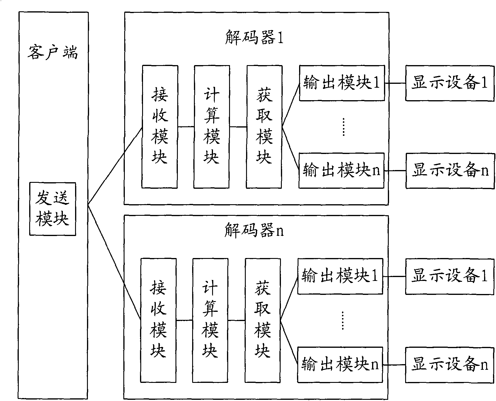
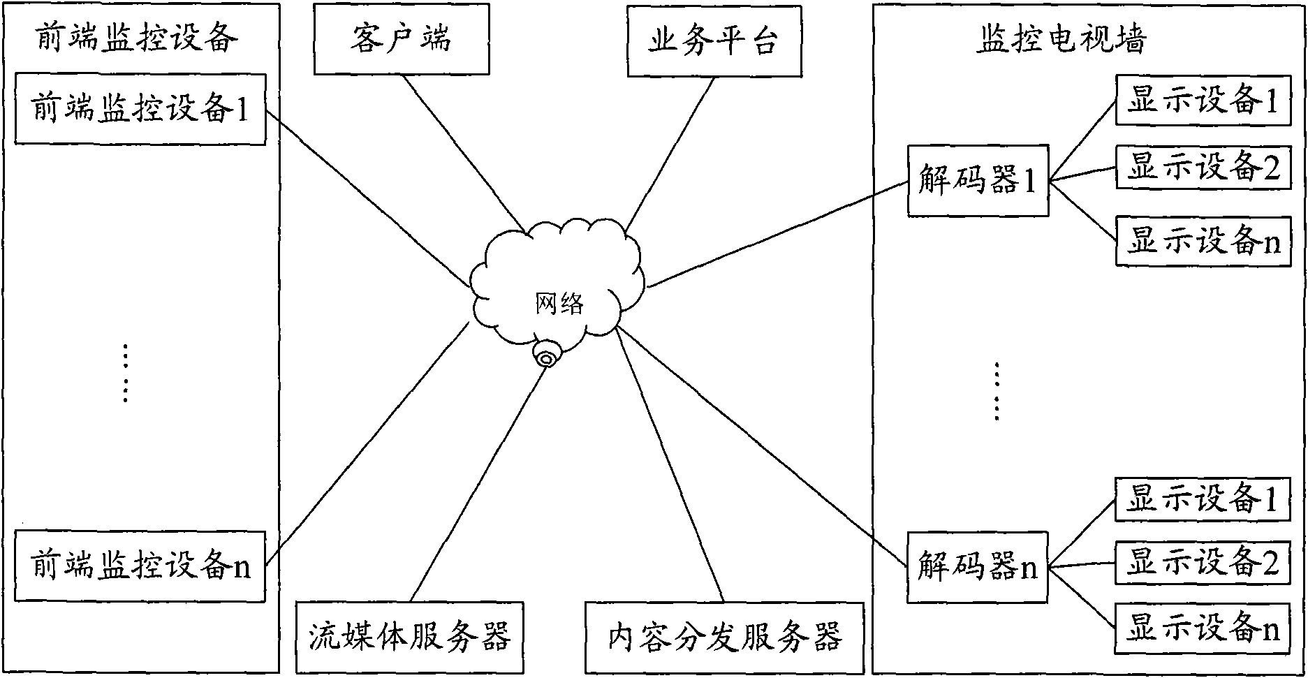
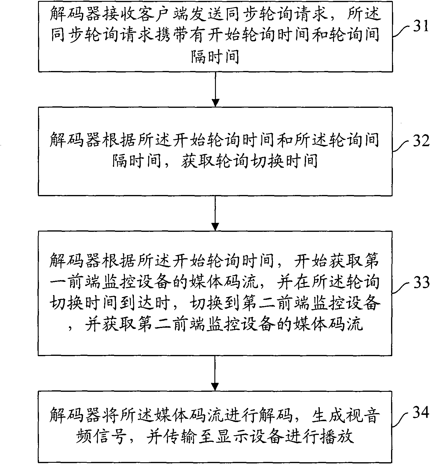
[0052]The present invention aims at that in the existing video monitoring system, the decoder cannot poll and play and switch the media code stream output by the front-end monitoring equipment at the same time, so that the user cannot conveniently observe the changes of different monitoring points, and the monitoring effect of the TV wall is not good. The problem is to provide a method, a decoder and a monitoring system capable of simultaneously polling, playing and switching the media stream output by the front-end monitoring equipment, and realizing synchronous polling of the decoder.

[0053] like figure 1 As shown, it is a schematic structural diagram of a system for realizing synchronous polling of decoders according to the prese...


PUM


Abstract

The invention provides a method, a decoder and a monitoring system for realizing decoder synchronous polling, wherein the method comprises the following steps that: the decoder receives a synchronous polling request sent by a client, and the synchronous polling request carries starting polling time and polling interval time; the decoder acquires polling switching time according to the starting polling time and the polling interval time; the decoder starts to acquire a medium code stream of first front-end monitoring equipment according to the starting polling time, and the decoder is switched to second front-end monitoring equipment in a polling mode when the polling switching time arrives and acquires a medium code stream of the second front-end monitoring equipment; and the decoder decodes the medium code streams, generates a video-audio signal, and transmits the signal to display equipment to play. The method, the decoder and the monitoring system realize that a plurality of the decoders carry out polling play and switch on the media code streams of the front-end monitoring equipment at the same time.

Description

technical field [0001] The invention relates to the field of video monitoring, in particular to a method for realizing synchronous polling of decoders, a decoder and a monitoring system. Background technique [0002] The video surveillance system has developed relatively maturely and has been widely used. Video surveillance is widely used in many occasions because of its intuition, convenience, and rich information content. In recent years, with the rapid development of computer, network, image processing and transmission technology, video surveillance technology has also made great progress. [0003] Existing video monitoring systems usually use front-end monitoring equipment to encode the video images collected by them, convert them into media code streams, and transmit them to the decoder of the TV wall. One decoder can receive media codes from multiple front-end monitoring devices. The video image format of the media code stream of multiple front-end monitoring devices ...

Claims


Application Information

Patent Timeline
Patent Type & Authority Applications(China)
IPC IPC(8): H04N7/52H04N7/18H04N7/26
CPCH04N7/26H04N7/18H04N7/181H04N7/52H04L12/403
Inventor 黄亮文良辉霍东风关君
Owner ZTE CORP
Why Eureka
Try Eureka