Vacuum line

A technology of vacuum pipelines and pipelines, applied in the direction of pipes/pipe joints/pipes, shock absorbers, adjustable connections, etc., which can solve the problems of weakening the transmission of vibration and affecting functions.

Inactive Publication Date: 2009-12-02
OERLIKON LEYBOLD VACUUM
View PDF1 Cites 5 Cited by
  • Summary
  • Abstract
  • Description
  • Claims
  • Application Information

AI Technical Summary

Problems solved by technology

Thus, the transmission of vibrations is damped only over a rather limited length, which can considerably a

Method used


Image

  • Vacuum line
  • Vacuum line
  • Vacuum line

Examples


Embodiment Construction

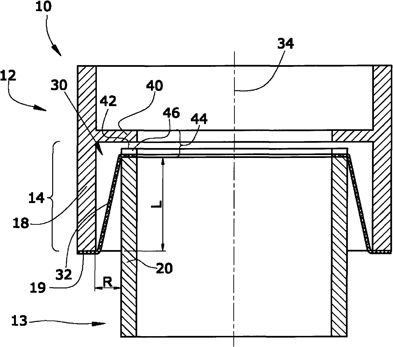
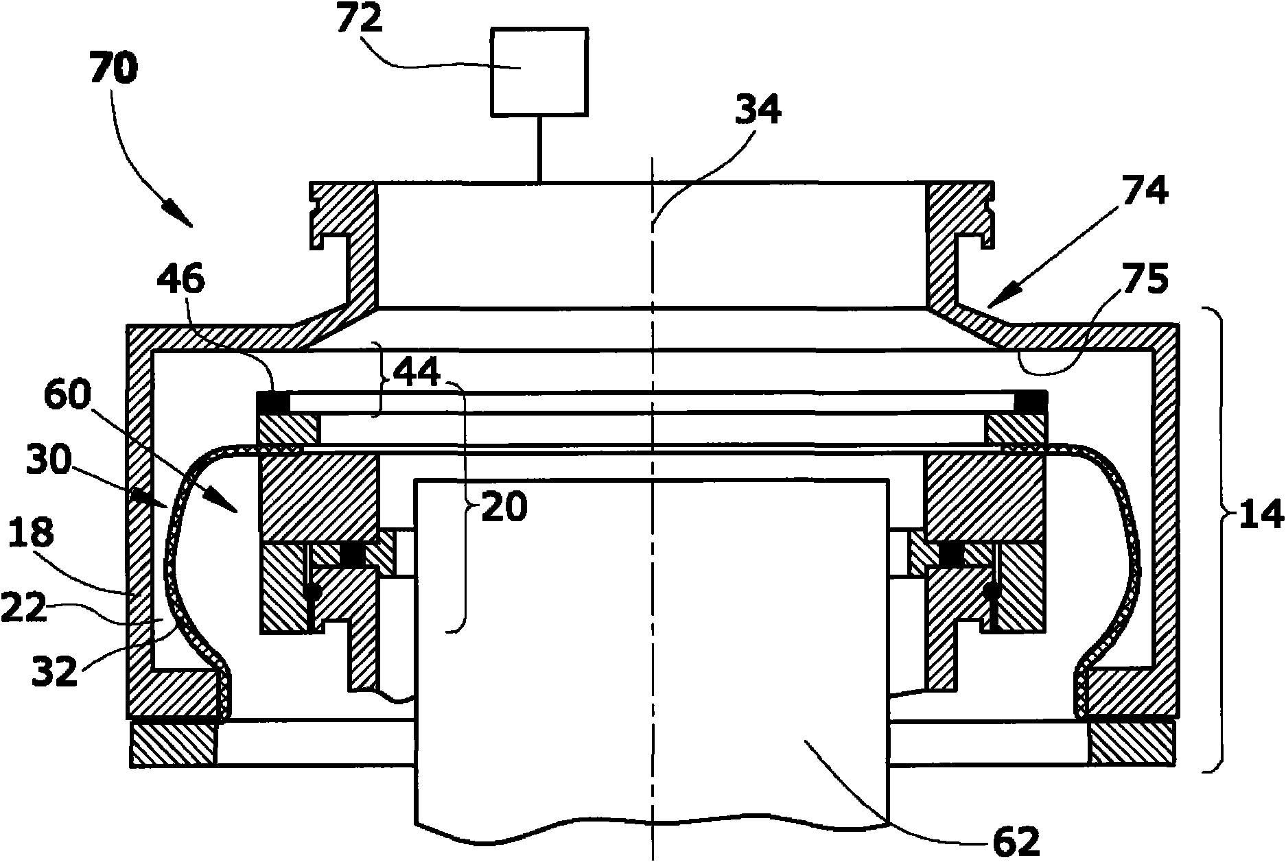
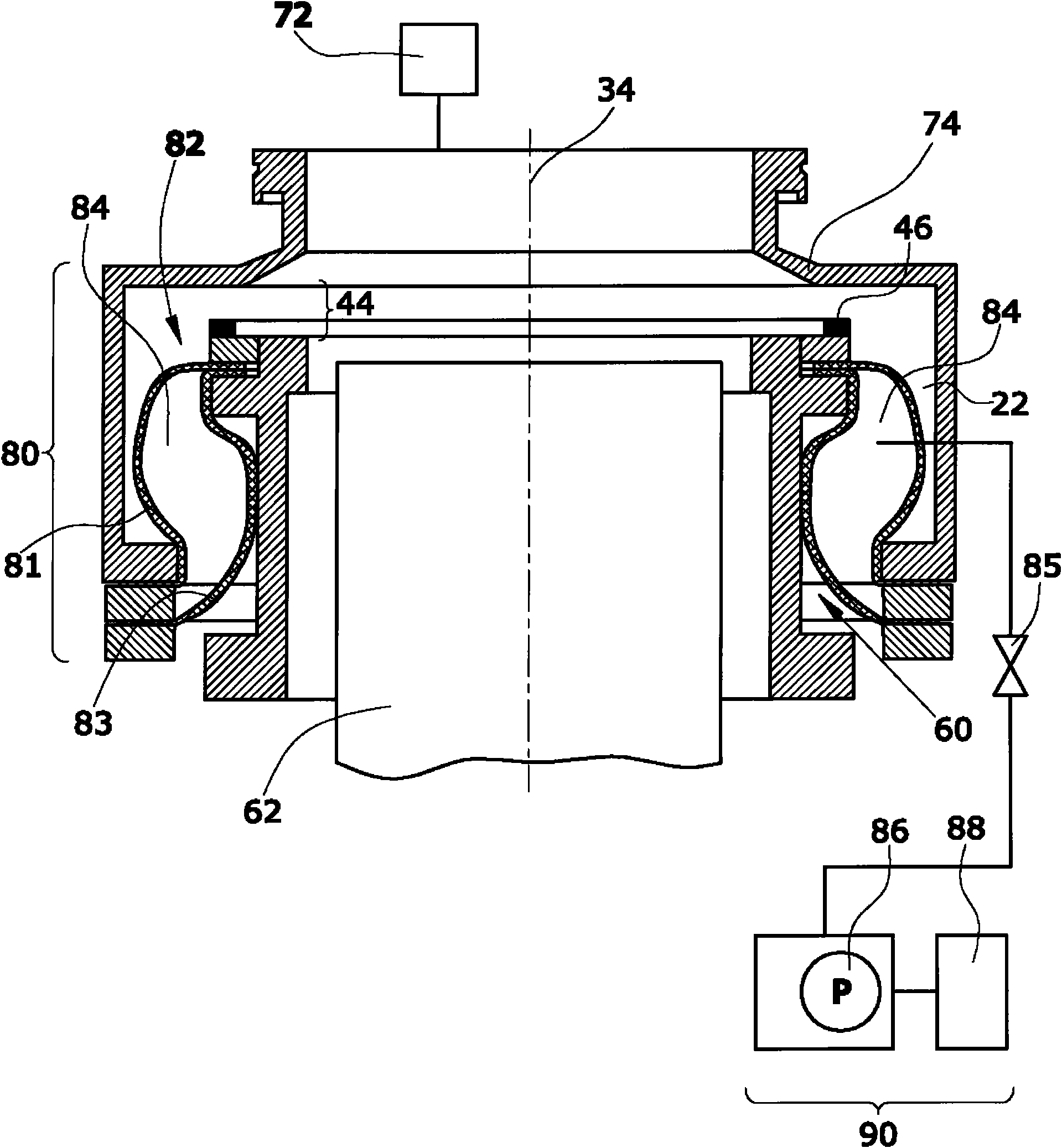
[0023] figure 1 A vacuum line 10 is schematically shown formed from two line parts 12 , 13 which are connected to one another via a vibration damper 14 . In the operating state, negative pressure is distributed in the vacuum line 10 and atmospheric pressure is distributed outside the vacuum line 10 .

[0024] The upper piping part 12 includes a vertical outer tube 18 into which a vertical inner tube 20 fits. The diameter of the outer tube 18 and inner tube 20 may be circular, but need not be. The cross-sectional profile of the outer tube 18 and the inner tube 20 may be cylindrical, but need not be.

[0025] The opening edge 42 of the inner tube 20 is connected with the opening edge 19 of the outer tube 18 through a flexible stretch sleeve 30, which is formed by a flexible but inelastic or little elastic sleeve hose 32. form. The opening edges of the sleeve hose 32 are connected in a vacuum-tight manner to the corresponding opening edges 19 , 42 of the outer tube 18 and the...


PUM


Abstract

The invention relates to a vacuum line (10) comprising two line parts (12, 13) connected by a vibration damper (14). The vibration damper (14) is formed by a vertical outer tube (18) and a vertical inner tube (20), the inner tube (20) being at a distance from the outer tube (18). A flexible traction collar (30) is fixed between the opening edges (19, 42) of the outer tube (18) and the inner tube (20), said collar connecting the two opening edges (19, 42) between the inner tube (20) and the outer tube (18) in a vacuum-tight manner. In this way, a vibration damper with good damping properties is created.

Description

technical field [0001] The invention relates to a vacuum line comprising two line parts connected by a vibration damper. Background technique [0002] In the field of vacuum technology, vibration dampers are used to isolate vibrations in vacuum connections, especially when the transmission of vibrations generated by vacuum pumps to connected vibration-sensitive receivers, such as electron microscopes, is avoided or must be avoided. [0003] A turbomolecular vacuum pump is known from German DE 100 01 509 A1, which comprises a high-vacuum flange which is separated from the pump components by vibration dampers. The vibration damper is a corrugated metal bellows with a separate outer supporting rubber sheath. The rubber boot supports the high vacuum flange axially against the pump components and is therefore rather rigid. Thus, the transmission of vibrations is damped only over a rather limited length, which can considerably affect the function of sensitive equipment such as e...

Claims


Application Information

Patent Timeline
IPC IPC(8): F16L27/10F04D29/66
CPCF16F15/02F16L27/1021F04D29/668F04D29/601F16F7/00F04D19/04F04D29/66F16L27/107
Inventor 海因里希·恩伦德尔
Owner OERLIKON LEYBOLD VACUUM
Why Eureka
Try Eureka