Wingtip eddy diffusion device

A diffusion device and wingtip technology, applied in the direction of wing adjustment, heat reduction structure, etc., to achieve the effect of small size, excellent comprehensive performance, and small increase in structural weight

Inactive Publication Date: 2009-12-09
BEIHANG UNIV
View PDF0 Cites 32 Cited by
  • Summary
  • Abstract
  • Description
  • Claims
  • Application Information

AI Technical Summary

Problems solved by technology

[0004] Among the above several devices, the drag reduction effect of the wingtip sail may be the best. However, the maximum drag reduction effect of the wingtip sail is based on the consideration of va

Method used


Image

  • Wingtip eddy diffusion device
  • Wingtip eddy diffusion device
  • Wingtip eddy diffusion device

Examples


Embodiment Construction

[0018] The present invention will be further described in detail below with reference to the drawings and embodiments.

[0019] In order to solve the above shortcomings, the present invention proposes a wingtip vortex diffusion device that can reduce the induced drag of the aircraft and improve the lift-drag ratio.

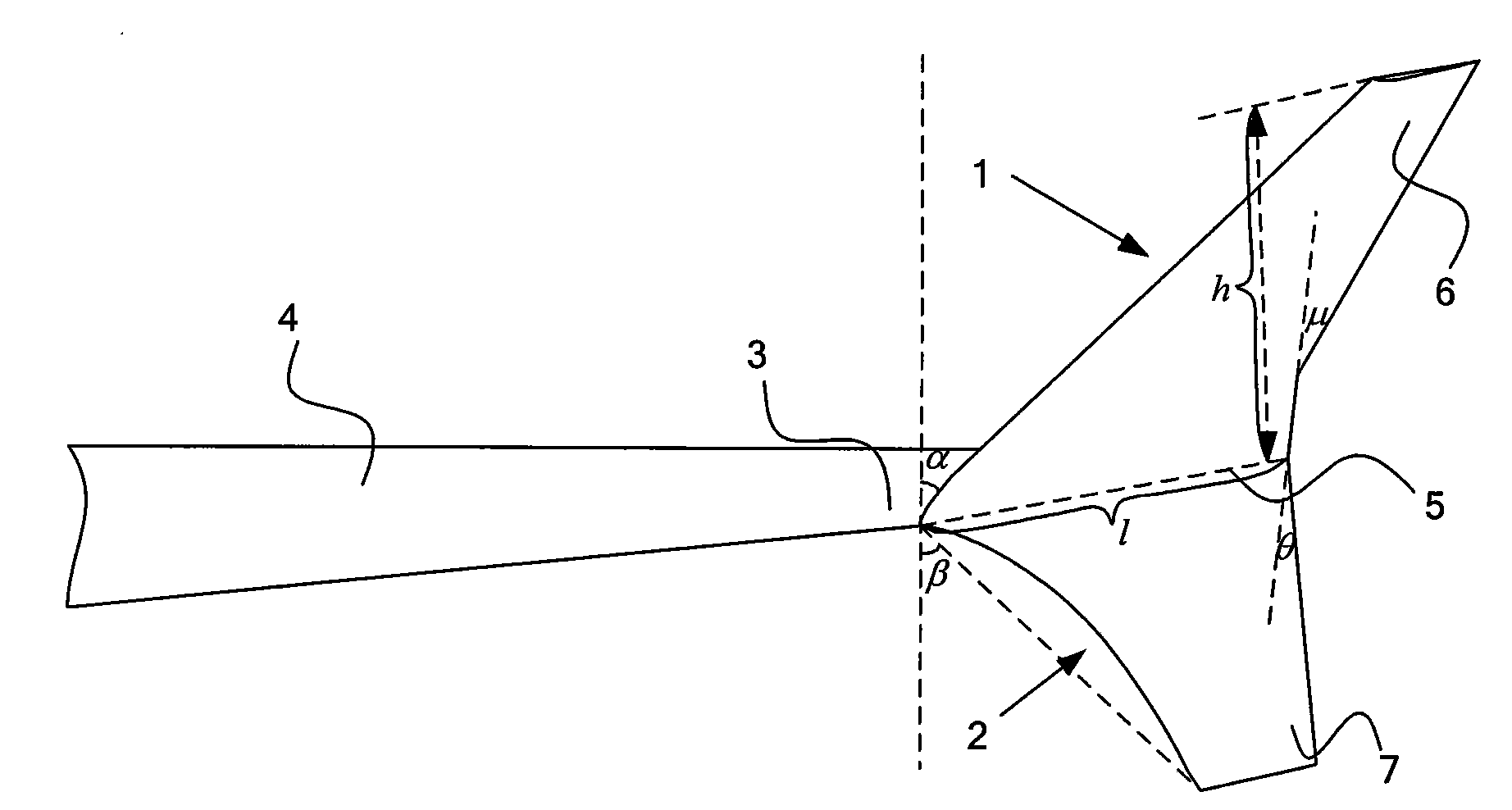
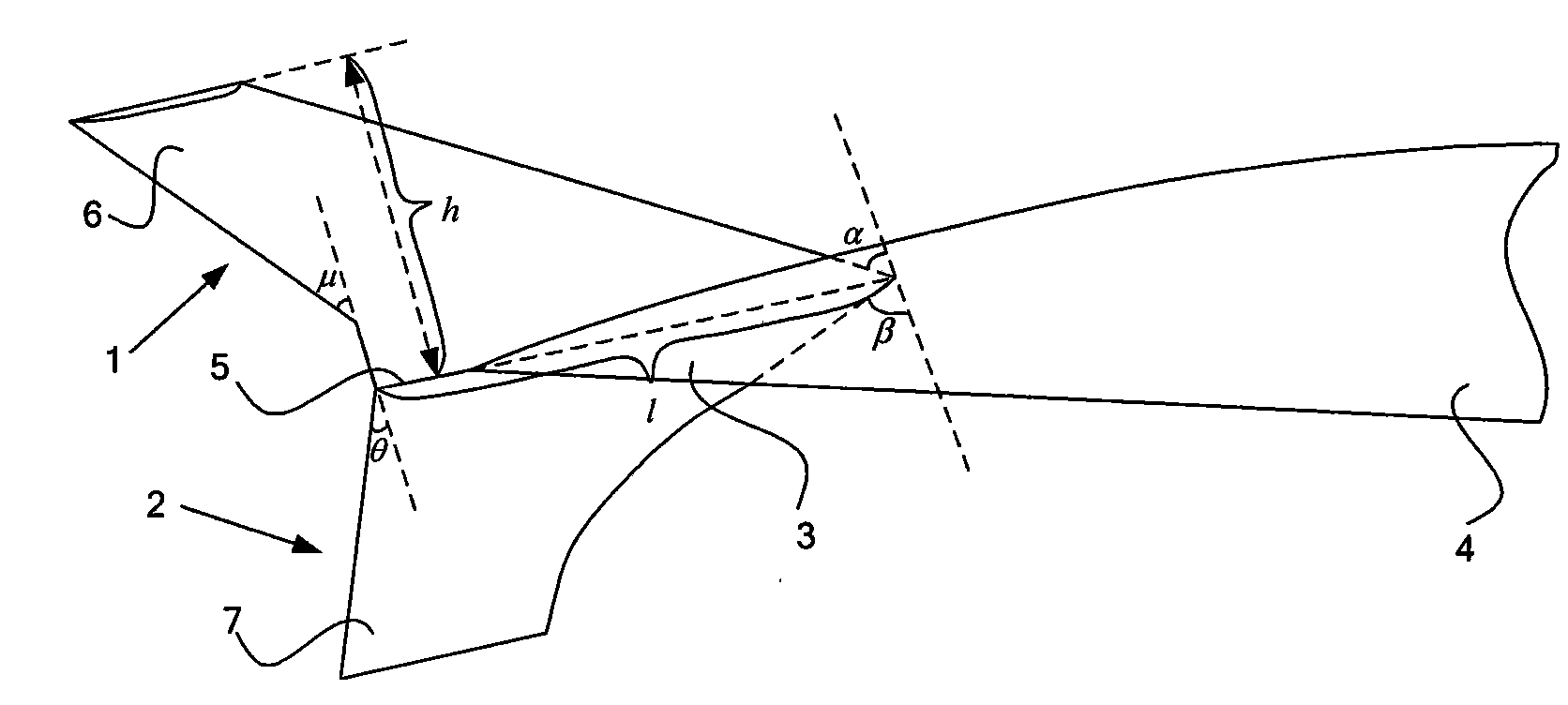
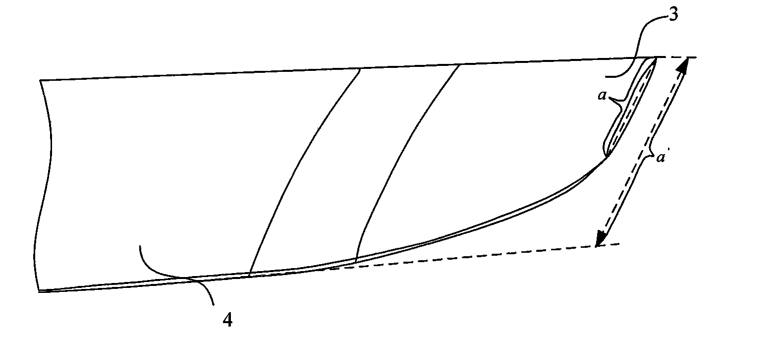
[0020] The invention is a wingtip vortex diffusion device, such as figure 1 , figure 2 , image 3 As shown, it is composed of an upper winglet 1 and a lower winglet 2. The span of the upper winglet h is between 400 and 500mm, and the leading edge sweep angles α and β of the upper winglet 1 and the lower winglet 2 are between 60 and 70 degrees, and both are larger than the rear of the wing 4. Sweep angle, the trailing edge sweep angle μ and θ of the upper winglet 1 and the lower winglet 2 are between 10 and 50 degrees, so that the airflow velocity on the two winglets is greater than the incoming flow velocity, and the upper winglet 1 and the lower winglet 2 The airfo...


PUM


Abstract

The invention relates to a wingtip eddy diffusion device, comprising an upper winglet and a lower winglet which play the role of an end plate to block bottom wing surface air current from flowing to the upper wing surface; the upper winglet and the lower winglet are both of symmetrical airfoil profile; the symmetrical airfoil profile can avoid intense shock wave under supercritical air current condition, extra wave drag; certain deflection exists in wingtips of corresponding wings of the two winglets, thus improving lifting force of wings. The invention has the advantages of weakening wingtip eddy diffusion and trailing vortex intensity, downwash field of wingtips of wings and induced drag.

Description

Technical field [0001] The invention belongs to the field of civil aircraft, and in particular is a wingtip vortex diffusion device. Background technique [0002] For most large civil airliners that have not undergone wingtip aerodynamic improvement, the induced drag during cruise accounts for more than 30% of the aircraft's total drag. The induced drag at low speeds and high angles of attack will be greater, and sometimes even account for the total drag. Around 70%. Therefore, it is necessary to improve the aerodynamics of the wing tips to reduce induced drag and improve the aerodynamic efficiency of the aircraft, thereby improving the fuel economy and flight performance of the aircraft. [0003] To reduce the induced drag, it is necessary to try to eliminate the concentrated vortex at the wing tip, so that the wash flow has a uniform distribution. Generally, the induced drag can be reduced by increasing the aspect ratio of the wing. However, this has to pay the price of increas...

Claims


Application Information

Patent Timeline
IPC IPC(8): B64C3/36B64C3/38
Inventor 钱光平刘沛清张大伟吴洋秦晓辉
Owner BEIHANG UNIV
Why Eureka
Try Eureka