
Portable active hydraulic tester and test method

A hydraulic tester, a portable technology, is applied in the testing of fluid pressure actuation systems, fluid pressure actuation devices, mechanical equipment, etc., which can solve the problems of difficult connection and expensive sensor testing, and achieve low cost, easy connection, and testing. precise effect

Inactive Publication Date: 2009-12-09
杨成刚 +1
View PDF0 Cites 15 Cited by
  • Summary
  • Abstract
  • Description
  • Claims
  • Application Information

AI Technical Summary

Problems solved by technology

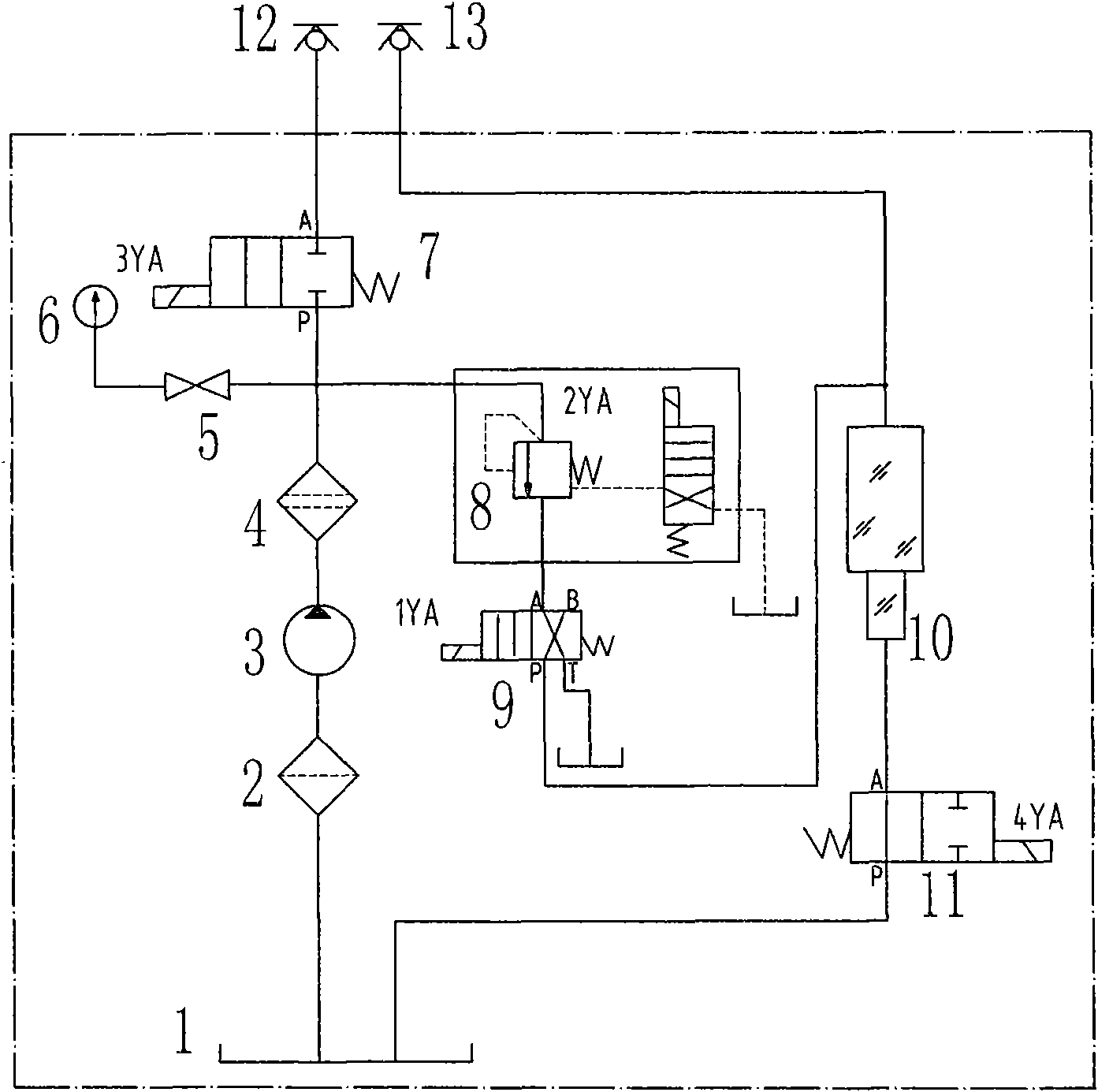
[0003] The technical problem to be solved by the present invention is to aim at the defects of the prior art using LabVIEW software simulation test and the conventional tester can only test a branch of the hydraulic system, and the connection is difficult, and the cost of using the sensor test is expensive. One is to provide a It is easy to connect, accurate in test, low in cost, and widely applicable. It calibrates its own parameters according to the parameters of the hydraulic system under test, records changes in the pressure and flow of the hydraulic system under test, and provides accurate spare parts information for the hydraulic system under test. The second is to provide a pressure test port connection between the tester and the hydraulic system (or hydraulic components) under test, which can realize the hydraulic components and hydraulic components of the hydraulic system under test (except hydraulic pumps). The performance test of accessories, and arrange the sequence of spare parts and replacement time, easy to operate test method with portable active hydraulic tester

Method used


Image

  • Portable active hydraulic tester and test method
  • Portable active hydraulic tester and test method
  • Portable active hydraulic tester and test method

Examples


Embodiment Construction

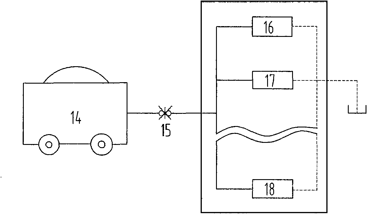
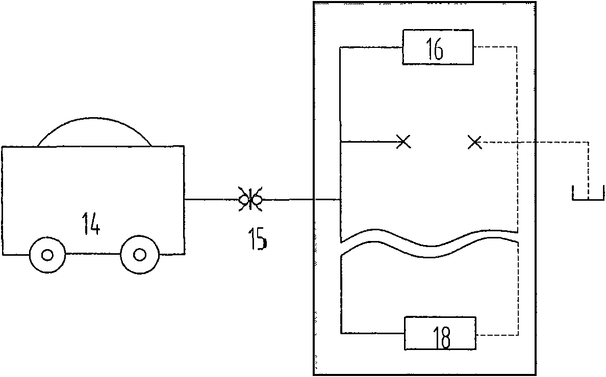
[0021] The present invention will be further described below in conjunction with the accompanying drawings.

[0022] See figure 1 , a portable active hydraulic tester, which is composed of a filter, a hydraulic pump, an electromagnetic reversing valve, an electromagnetic overflow valve, and a measuring cylinder. The connection structure is: the coarse filter 2 is connected to the oil inlet of the hydraulic pump 3, and the oil outlet of the hydraulic pump 3 is connected to the inlet of the fine filter 4; the outlet of the fine filter 4 is respectively connected to the pressure gauge switch 5. The inlet connection of the normally off two-position two-way electromagnetic reversing valve 7 and the electromagnetic overflow valve 8; the pressure gauge switch 5 is connected with the pressure gauge 6; the normally-off two-position two-way electromagnetic reversing valve 7 is quickly The joint 12 is connected; the oil return port of the electromagnetic overflow valve 8 is connected wi...


PUM


Abstract

The invention discloses a portable active hydraulic tester and a test method. A coarse filter of the tester is connected with a hydraulic pump, and the hydraulic pump is connected with a fine filter; the fine filter is connected with a normally-off two-position two-way electromagnetic directional valve, a pressure gauge switch and an electromagnetic relief valve; the normally-off two-position two-way electromagnetic directional valve is connected with a quick connector; the electromagnetic relief valve is connected with a two-position four-way electromagnetic directional valve, and the two-position four-way electromagnetic directional valve is connected with an oil return quick connector and a metering cylinder; the two-position four-way electromagnetic directional valve is connected with an oil tank; the metering cylinder is connected with a normally-on two-position two-way electromagnetic directional valve; and the normally-on two-position two-way electromagnetic directional valve is connected with the oil tank. The test method comprises the following steps: debugging the pressure and flow parameter calibrated by the tester; testing the pressure and flow parameters under the condition that tested hydraulic systems and components are removed respectively, drawing a coordinate graph and analyzing a test result; and completing the performance calibration of a new-manufactured hydraulic system and the performance testing of an online hydraulic system, listing the sequence of hydraulic component spare parts, and removing faults. The tester and the method have simple, convenient and fast operation.

Description

Technical field: [0001] The invention relates to a portable active hydraulic tester and a test method used in various fields such as hydraulic system manufacture, component manufacture, hydraulic system use and maintenance. Background technique: [0002] The test of the existing international and domestic hydraulic system testers is to use the virtual test system developed by LabVIEW software or the hydraulic system tester to be connected in series and connected to a branch of the hydraulic system to measure parameters such as pressure, flow, temperature, etc. changes. It is difficult, if not impossible, to test all the components in a hydraulic system. Therefore, international and domestic conventional testing methods can only test hydraulic components or only part of a branch circuit of a hydraulic system, and the connection is quite difficult. From the actual test point of view, due to the various types and specifications of the hydraulic system and hydraulic components...

Claims


Application Information

Patent Timeline
Patent Type & Authority Applications(China)
IPC IPC(8): F15B19/00
Inventor 杨成刚赵静一
Owner 杨成刚
Learn More