High-temperature phase change heat accumulation pipe and heat accumulator

A technology of high-temperature phase change and heat storage tubes, applied in heat storage equipment, indirect heat exchangers, heat exchanger types, etc., can solve the problems of small heat storage, large heat storage volume, unstable heat release, etc., and achieve heat storage The effect of high density and small volume

Inactive Publication Date: 2009-12-09
HARBIN ENG UNIV
View PDF2 Cites 13 Cited by
  • Summary
  • Abstract
  • Description
  • Claims
  • Application Information

AI Technical Summary

Problems solved by technology

However, the existing solar heat storage devices have small heat storage capacity, large heat storage volume, and unstable heat release.

Method used


Image

  • High-temperature phase change heat accumulation pipe and heat accumulator
  • High-temperature phase change heat accumulation pipe and heat accumulator
  • High-temperature phase change heat accumulation pipe and heat accumulator

Examples


Embodiment Construction

[0026] The present invention is described in more detail below in conjunction with accompanying drawing example:

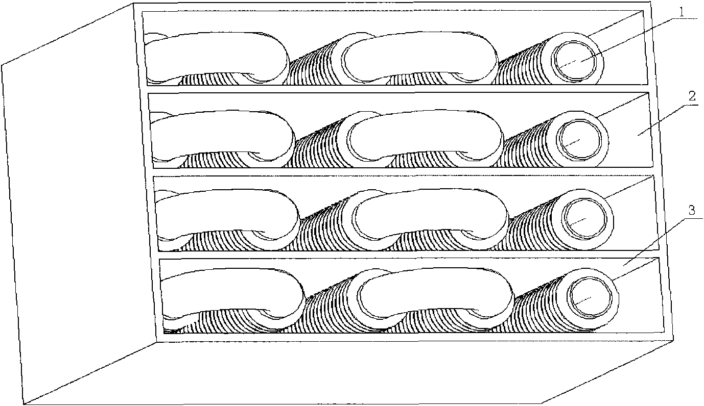
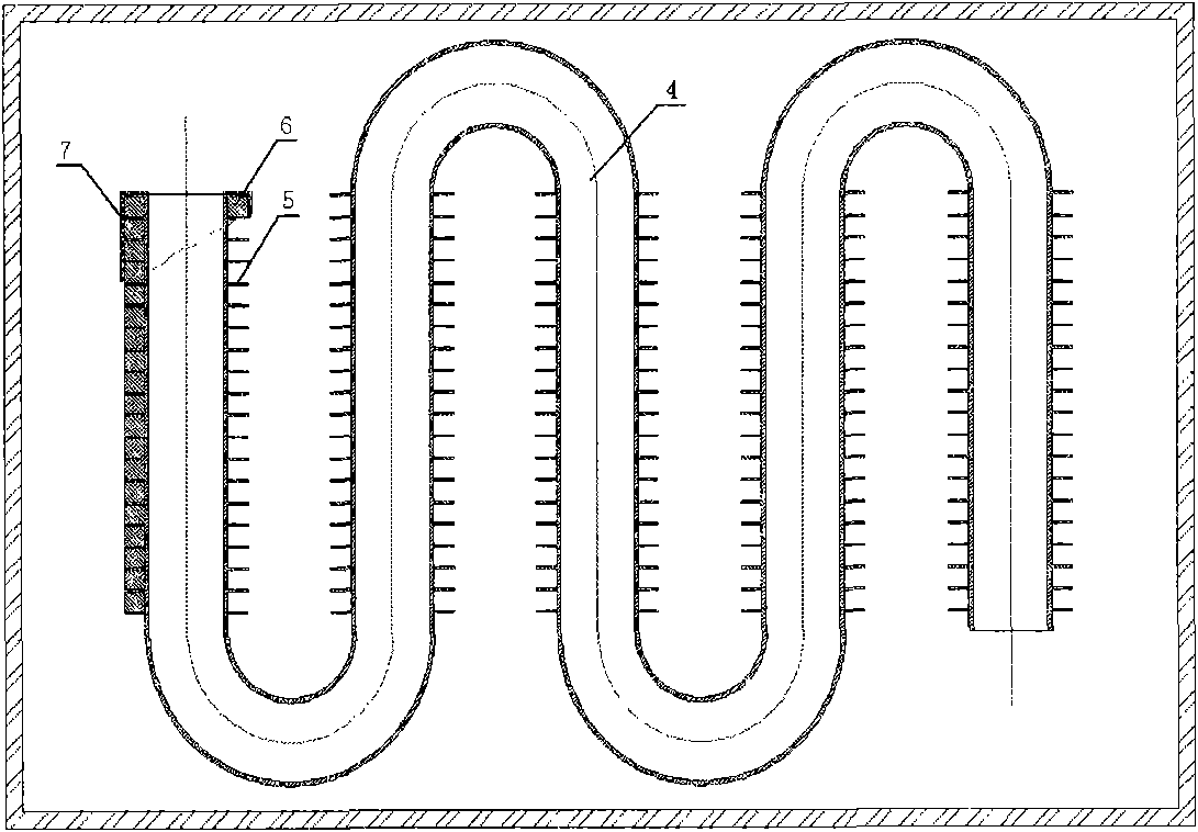
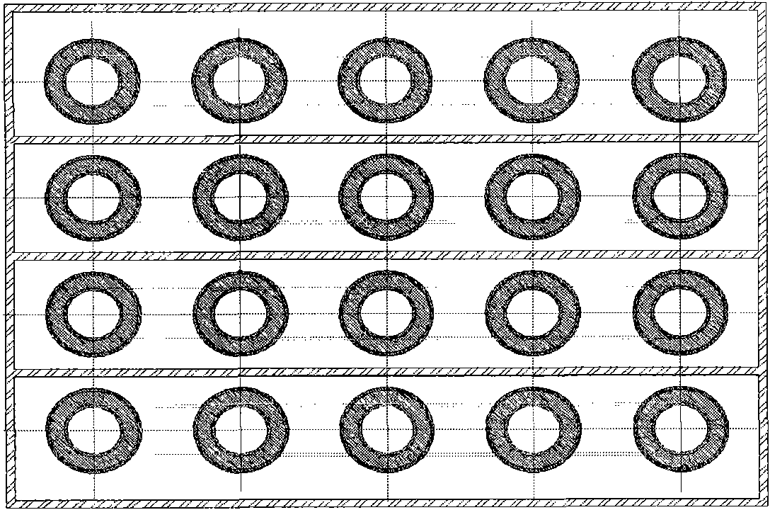
[0027] combine figure 2 - Fig. 7, the composition of the high-temperature phase-change heat storage tube of the present invention includes a serpentine working medium conduit 4, with annular fins 5 on the outside of the serpentine working medium conduit, fan ring heat storage units 6 are installed between the annular fins, and fan ring heat storage units 6 are installed between the annular fins. The ring heat storage unit is filled with a phase change material, and a heat insulating material 7 is arranged on the periphery. The mole percent composition of the phase change material is: 80.5% LiF, 19.5% CaF 2 . The fan ring thermal storage unit is surrounded and composed of an upper end cover 10, a lower end cover 11, an outer ring plate 12, an inner ring plate 13, a left side plate 14 and a right side plate 15.

[0028] combine figure 1 The composition of the h...


PUM

PropertyMeasurementUnit
heightaaaaaaaaaa
melting pointaaaaaaaaaa

Abstract

The invention provides a high-temperature phase change heat accumulation pipe and a heat accumulator. The heat accumulator comprises a casing and a high-temperature phase change heat accumulation pipe arranged in the casing. The high-temperature phase change heat accumulation pipe is characterized in that the high-temperature phase change heat accumulation pipe comprises an S-shaped working medium conduit, the outer side of the S-shaped working medium conduit is provided with annular fins, a fan ring heat accumulation unit is installed between the annular fins, a phase change material is filled in the fan ring heat accumulation unit, and a working medium is installed in the S-shaped working medium conduit and is mixed molten salt. The invention utilizes the solid-liquid phase change process of the phase change material to complete the storage and release of energy, has the advantages of small volume, large heat accumulation density and constant-temperature heat release and has a certain development prospect.

Description

(1) Technical field [0001] The invention relates to an energy storage and release device, in particular to a novel high-temperature phase change heat storage device. (2) Background technology [0002] At present, our country and many countries in the world are facing the contradiction that the power supply cannot keep up with the needs of economic development, the peak-valley load difference of the power grid is large, and the valley power utilization rate is not high. Compared with conventional energy, solar energy is a huge energy treasure house, which is clean, non-polluting, and easy to use, especially in some high mountain areas, such as Gansu, Qinghai, Tibet and other places in my country, where the intensity of solar radiation is high, while other energy sources are in short supply , so the use of solar energy is more common, but the solar radiation reaching the earth's surface has a very low energy density, and is affected by regular changes in geography, day and nigh...

Claims


Application Information

Patent Timeline
Patent Type & Authority Applications(China)
IPC IPC(8): F28D20/02F28F1/24C09K5/06
CPCY02E60/145F28D20/02Y02E60/14
Inventor 周春良郑洪涛徐鑫王嘉宁
Owner HARBIN ENG UNIV
Why Eureka
Try Eureka