
Optical imaging system and manufacturing method thereof

A technology of an optical imaging system and a manufacturing method, applied in the optical field, can solve the problems of difficulty in processing and inspection, index limitation in increasing the field of view, and the secondary mirror cannot be independently inspected, etc., and achieves the effect of improving image quality and field of view.

Inactive Publication Date: 2009-12-09
SHANGHAI ENG CENT FOR MICROSATELLITES
View PDF0 Cites 13 Cited by
  • Summary
  • Abstract
  • Description
  • Claims
  • Application Information

AI Technical Summary

Problems solved by technology

In the design result, both the primary and secondary mirrors are aspherical, and the primary mirror is a hyperboloid close to a paraboloid, and the secondary mirror is a hyperboloid. The inspection of the two must cooperate with each other to complete, which brings great difficulty to the processing inspection.
In addition, the secondary mirror is a hyperboloid, and its conic coefficient K is mostly between -1 and -6. Because it is usually the result of computer optimization, it has uncertainty, which makes it impossible to carry out independent inspection of the secondary mirror.
One of the improvements to the RC system is to add a correction lens group, but this will not change the relative position of the primary and secondary mirror focal points, and the indicators for improving image quality and increasing the field of view are greatly limited

Method used


Image

  • Optical imaging system and manufacturing method thereof
  • Optical imaging system and manufacturing method thereof
  • Optical imaging system and manufacturing method thereof

Examples


Embodiment Construction

[0028] Preferred embodiments of the present invention will be described in detail below in conjunction with the accompanying drawings.

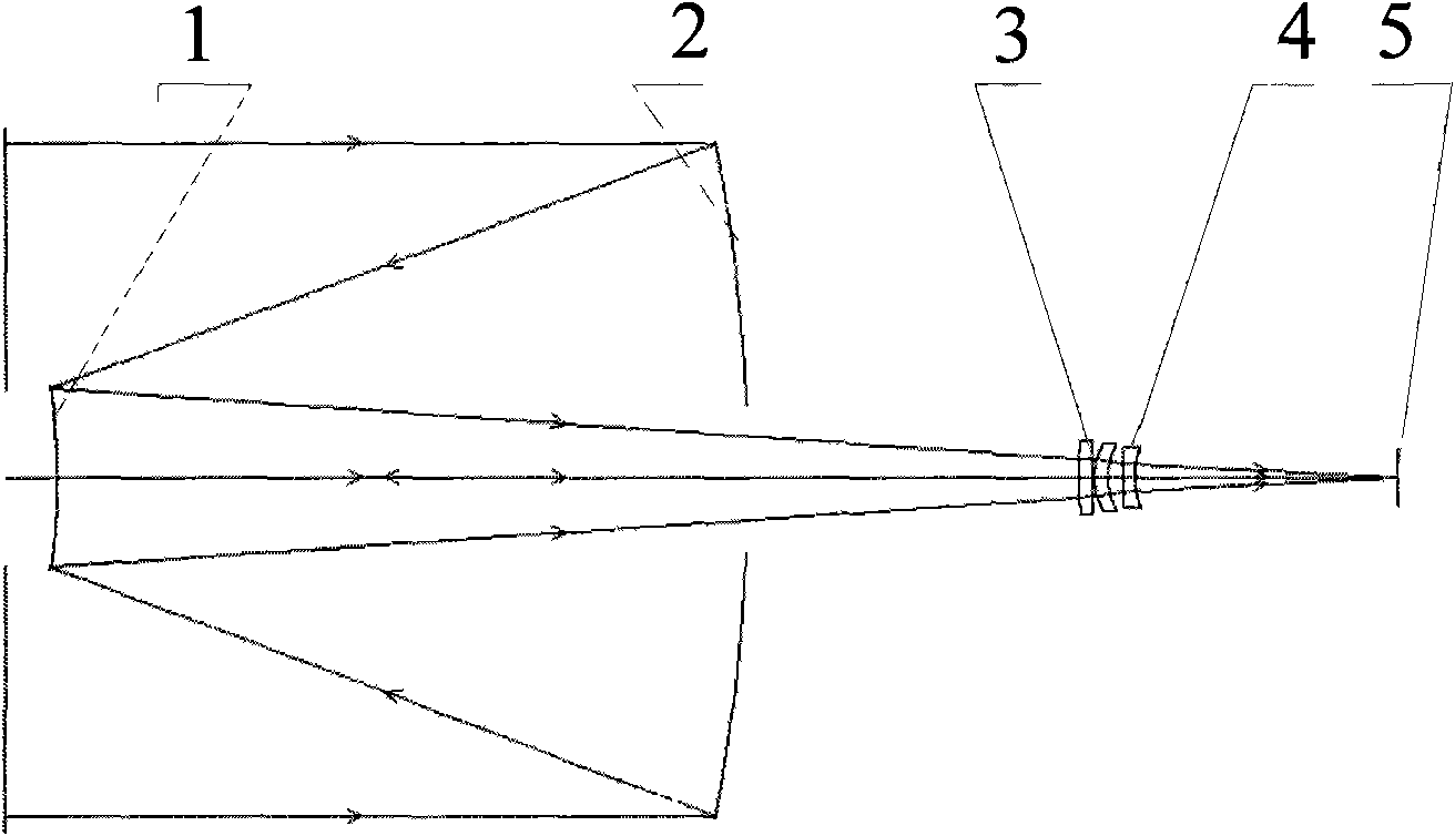
[0029] see image 3 , The present invention discloses an optical imaging system, comprising a secondary mirror 1, a primary mirror 2, a correction lens group 3, an image field correction mirror 4, and a focal plane 5 arranged in sequence. The primary mirror 2 is a paraboloid; the secondary mirror 1 is a hyperboloid, and the conical coefficient of the hyperboloid of the secondary mirror 1 is determined according to the refractive index of the secondary mirror material and the wavelength of the inspection beam. In this embodiment, the conical coefficient of the hyperboloid of the secondary mirror is the inverse of the square of the refractive index of the material of the secondary mirror.

[0030] see Figure 4 , one side of the secondary mirror 1 is a hyperbolic surface 11 , and the other side is a plane reflecting surface 12 . In the singl...


PUM


Abstract

The invention discloses an optical imaging system which comprises a secondary lens, a main lens, a correction lens group and an image field correction lens which are sequentially arranged. Four items of spherical aberration, coma aberration, astigmatism and image field curvature in monochromatic aberration are considered to be eliminated according to a third-order aberration theory. The main lens is a paraboloid; the secondary lens is a hyperboloid, and the conical coefficient of the hyperboloid of the secondary lens is determined according to the refractive index of the material of the secondary lens. Optimized by a computer, the image quality and the view field of the double reflection optical imaging system are obviously improved, and in the sights of a geometric spot diagram (SPOT), a modulation transfer function (MTF) and encircled energy (EE), the image quality of the optical imaging system basically reaches a diffraction limit.

Description

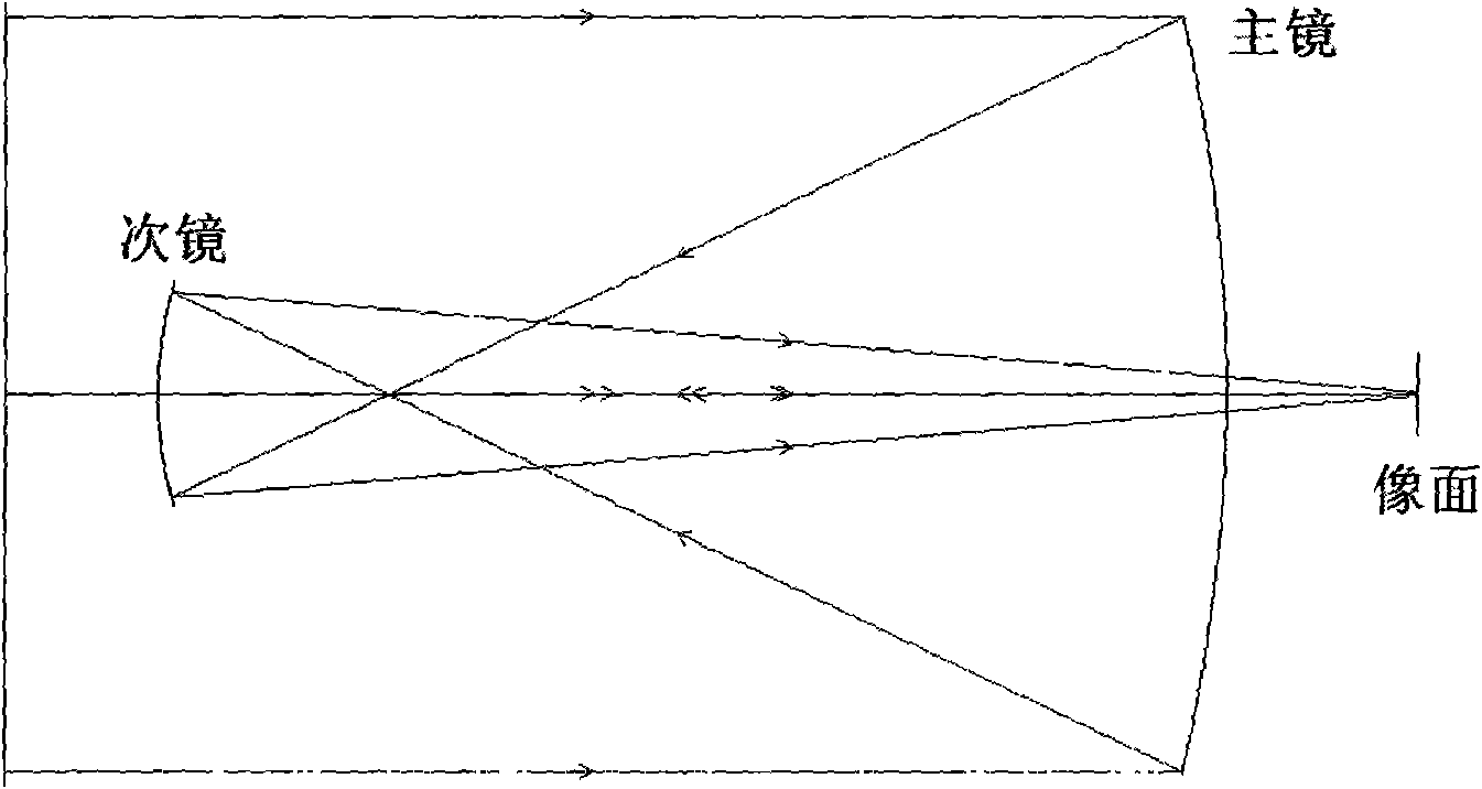
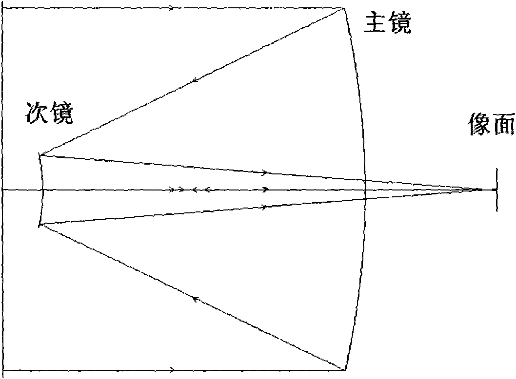
technical field [0001] The invention belongs to the field of optics, and relates to an optical imaging system, in particular to an optical system of a double retro-plus correction lens. In addition, the invention also relates to a manufacturing method of the optical system. Background technique [0002] Conventional double-reflective objectives have Gregorian systems (such as figure 1 shown), Cassegrain system (such as figure 2 shown) and R-C system. [0003] Among them, the feature of the Gregorian system is that the primary mirror is a paraboloid, the secondary mirror is an ellipsoid, the focus of the paraboloid of the primary mirror coincides with a focus of the ellipsoid of the secondary mirror, and the image is formed at another focus of the secondary mirror, and the system has an intermediate image point. Larger tube length; [0004] The primary mirror of the Cassegrain system is a paraboloid, and the secondary mirror is a hyperboloid. The focus of the paraboloid o...

Claims


Application Information

Patent Timeline
Patent Type & Authority Applications(China)
IPC IPC(8): G02B17/08G02B27/00B29D11/00
Inventor 郝沛明原育凯
Owner SHANGHAI ENG CENT FOR MICROSATELLITES
Learn More