Method for simulating blade flutter boundary of aviation turbine engine

A technology for engine blades and aviation turbines, used in 3D modeling, image data processing, special data processing applications, etc.

Inactive Publication Date: 2009-12-09
BEIHANG UNIV
View PDF0 Cites 73 Cited by
  • Summary
  • Abstract
  • Description
  • Claims
  • Application Information

AI Technical Summary

Problems solved by technology

There is currently no mature technology for simulating engine fan or compressor blade flutter

Method used


Image

  • Method for simulating blade flutter boundary of aviation turbine engine
  • Method for simulating blade flutter boundary of aviation turbine engine
  • Method for simulating blade flutter boundary of aviation turbine engine

Examples


Embodiment Construction

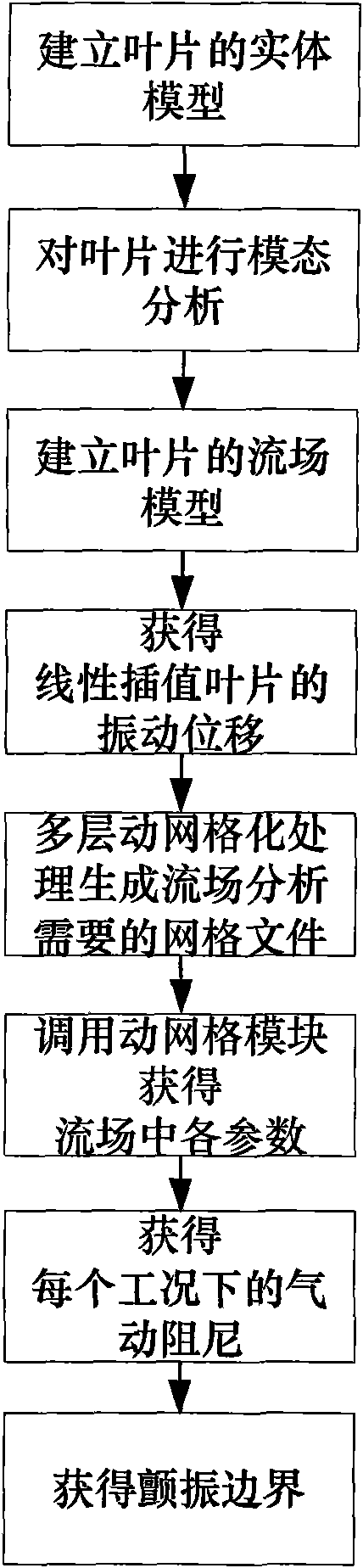
[0063] The present invention will be further described in detail with reference to the accompanying drawings and embodiments. The present invention is a method for simulating the flutter boundary of an aero turbine engine blade based on the energy method. The flow of the simulation method for the flutter boundary is as follows: figure 1 shown.

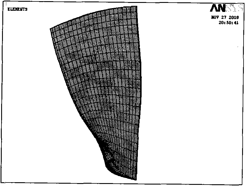
[0064] Step 1: Establish a solid model of the blade.

[0065] Create a 3D solid model of the engine fan blade to be analyzed.

[0066] Step 2: Perform modal analysis on the blade.

[0067] Import the established three-dimensional solid model of the engine fan blade into the finite element analysis tool ANSYS, and divide it into finite element elements, define the material and element properties, and add loads and constraints. Use the dynamic mode analysis in ANSYS to obtain the natural mode of the blade, extract the frequency and mode required for flow field analysis, and derive the finite element grid node information on the blade ...


PUM


Abstract

The invention discloses a method for simulating the blade flutter boundary of an aviation turbine engine, which is based on the principle of energy law and adopts a weak coupling method to design a flutter forecasting method, thus obtaining the blade flutter boundary of the engine by pneumatic damping value. The method comprises: first, a solid model of a blade is set up; then, modal analysis is carried out on the blade; after that, a flow field model of the blade is set up; the vibration displacement of the linear interpolation blade can be obtained, grid files needed by flow field analysis are generated by adopting multilayer dynamic mesh processing, a dynamic mesh module is invoked to obtain the parameters in the flow field, pneumatic damping is acquired under every working condition, and finally, the flutter boundary can be obtained. Based on the one-way weak coupling, the method greatly simplifies the calculation, saves the calculation cost, and can realize the pneumatic damping calculation under any frequency and different flow field states, thus having good engineering applicability.

Description

technical field [0001] The invention belongs to the field of aero-engine simulation, and in particular relates to a method for simulating the flutter boundary of an aero-turbine engine blade based on an energy method. Background technique [0002] After the 1990s, the development direction of aero-engines with high speed, high thrust-to-weight ratio, high applicability and durability, and low cost has become the mainstream trend. This trend makes the stage load of the turbofan engine compressor heavier and heavier, and the working environment of the fan and compressor blades is very severe. In aero-engines, vibration faults account for more than 60% of the total faults in the engine, and blade faults account for more than 70% of the vibration faults. Among them, blade failure caused by flutter accounts for a considerable proportion. If the fluid-solid coupling phenomenon of blade flutter can be effectively simulated, and the structure optimization scheme of the blade is pr...

Claims


Application Information

Patent Timeline
Patent Type & Authority Applications(China)
IPC IPC(8): G06F17/50G06T17/40G06T19/00
Inventor 张潇张小伟王延荣王蛟刘沛清
Owner BEIHANG UNIV
Why Eureka
Try Eureka