
LED display device and LED display screen case body

A technology for display devices and cabinets, applied in identification devices, static indicators, instruments, etc., can solve the problems of unreliable contact, easy failure, and limited cascade length.

Inactive Publication Date: 2009-12-09
幸琳
View PDF0 Cites 9 Cited by
  • Summary
  • Abstract
  • Description
  • Claims
  • Application Information

AI Technical Summary

Problems solved by technology

[0003] In the prior art, LED display devices are generally composed of several LED unit boards, each LED unit board includes a PCB board, and several LED light-emitting diodes, power supply lines, signal lines, resistors, capacitors, control chips, constant current, etc. are arranged on the PCB board. Chips, etc., due to the large number of electronic components and electronic circuits on the PCB, the wiring is very complicated, the contact is unreliable, and failures are prone to occur. Moreover, in the prior art, due to the limitations of the control chip used, the signal lines generally include Two or more, resulting in complex communication, mutual interference between lines, and limited cascading length

Method used


Image

  • LED display device and LED display screen case body
  • LED display device and LED display screen case body
  • LED display device and LED display screen case body

Examples


Embodiment 1

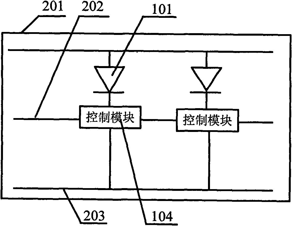
[0024] This embodiment provides an LED display device, the LED display device includes at least one LED unit board, a signal line, a power line and a ground line, the signal line, the power line and the ground line are set On the PCB board, for example, lines are arranged side by side.

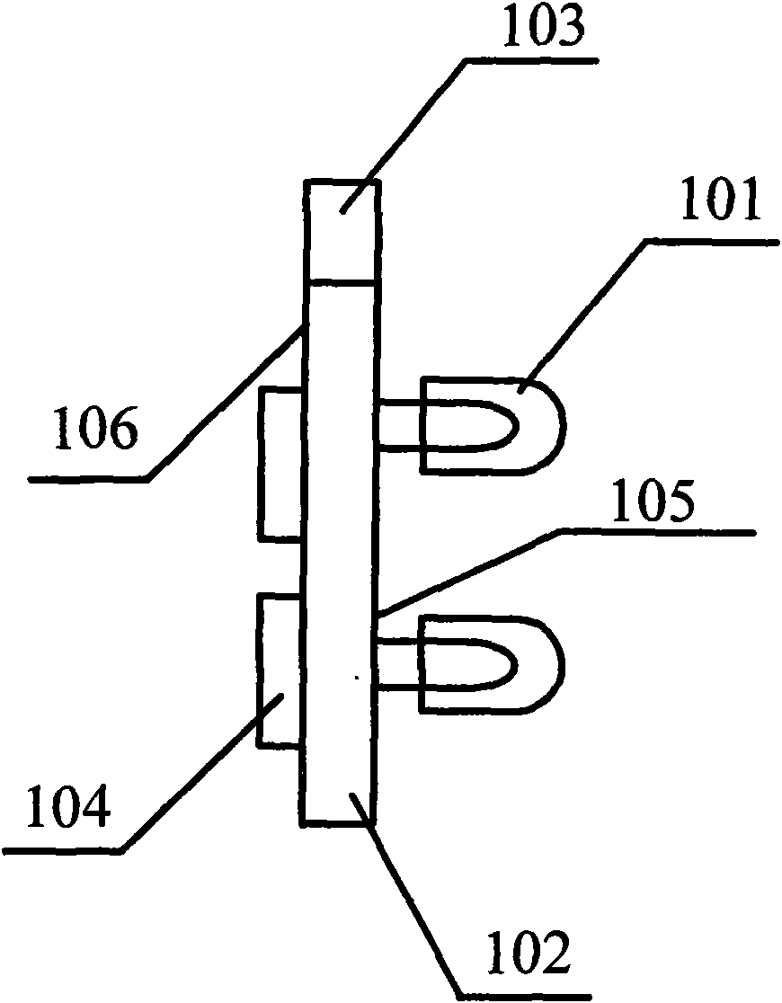
[0025] Such as figure 1 As shown, the LED unit board includes a PCB board 102, on the first side 105 of the PCB board 102, several groups of LED light-emitting diodes 101 are arranged; on the second side 106 of the PCB board 102, at least two single-line drive For the control chip 104, the first side 105 and the second side 106 are two opposite sides of the PCB 102, that is, two sides of the PCB for wiring that do not intersect each other. Each group of LED light-emitting diodes 101 and the single-line drive control chip 104 are respectively arranged on different two sides of the PCB board, so that the wiring of the PCB board can be simplified, the distribution is more reasonable, and materia...

Embodiment 2

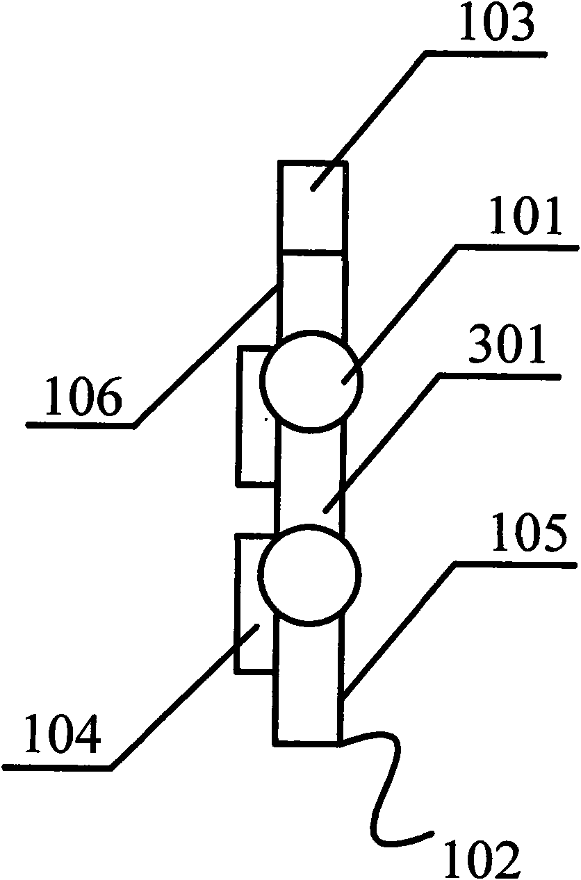
[0034] Such as image 3 As shown, on the basis of the above examples, each group of LED light-emitting diodes 101 is arranged on the first side 301 of the PCB 102, and the single-line drive control chip is arranged on the second side 106 of the PCB. Above, the first side 301 and the second side 106 are two adjacent sides on the PCB, and the side 301 and the side 106 intersect each other, that is, each group of LED light-emitting diodes is arranged on the On any side of the PCB 102 , the single-line drive control chip 104 is disposed on any side of the PCB 102 for wiring.

[0035] In this way, only LED light-emitting diodes are provided on the light-emitting surface of LED light-emitting diodes 101, which can make the horizontal occupation space of the LED unit board in this embodiment relatively small. The direction of one side is the ornamental surface, and almost only the LED light-emitting diodes can be seen, which makes the ornamental surface of the LED product beautiful....

Embodiment 3

[0038] On the basis of the above-mentioned embodiments, the shape of the LED unit board can be set as one of circular, elliptical, triangular, quadrilateral or pentagonal, for example, the LED unit board is triangular, triangular The LED unit boards can form LED display devices of any shape with each other. For another example, the LED unit board is quadrilateral, and the quadrilateral LED unit board is the most commonly used LED unit board. It is convenient and easy to assemble and meets the requirements of most LED display devices. Actual requirements, as another example, the LED unit board is circular, or oval, or pentagonal, and a circular, oval, or pentagonal LED unit board can meet the needs of some special occasions.


PUM


Abstract

The invention discloses an LED display device and an LED display screen case body. The LED display device comprises at least one LED unit board, a signal wire, a power wire and an earth wire; the LED unit board comprises a PCB, a plurality of groups of LEDs, at least two single-wire drive control chips and at least one connection part; each group of LEDs are arranged on the first lateral surface of the PCB, and each single-wire drive control chip is arranged on the second lateral surface of the PCB; each single-wire drive control chip is only provided with a signal input interface and a signal output interface, and the single-wire drive control chips are serially cascaded only through one control signal wire; the connection part is used for connecting the corresponding connection parts of other LED unit boards and fixedly arranged on the PCB; and the signal wire, the power wire and the earth wire are printed on the PCB respectively, and the adjacent wires are distributed in equal distance.

Description

technical field [0001] The invention relates to an LED illuminating device, in particular to an LED display device and an LED display box. Background technique [0002] The English of light-emitting diode is Light Emitting Diode (LED). Its basic structure is a piece of electroluminescent semiconductor material, placed on a shelf with leads, and then sealed with epoxy resin around it. When it is in the forward working state (that is, a forward voltage is applied to both ends), when the current flows from the anode to the cathode of the LED, the semiconductor material will emit light, and the intensity of the light is related to the magnitude of the current. For many years, LED has been playing an important role in the field of flat panel display, and relying on its unique advantages of high brightness, high strength, long life, splicing, convenience and flexibility, it can be displayed indoors and outdoors in large areas, especially in sports , Advertising, finance, exhibiti...

Claims


Application Information

Patent Timeline
IPC IPC(8): G09F9/33G09G3/32
Inventor 幸琳
Owner 幸琳
Learn More