Insulating pull rod for breaker

A technology of insulating pull rods and circuit breakers, which is applied in the direction of high-voltage air circuit breakers, circuits, electrical components, etc., can solve the problems of inconvenient, fast, efficient, labor-intensive, time-consuming and labor-intensive assembly, and reduce work efficiency, so as to solve the problem of external partial discharge deviation High and corona, improve work efficiency, improve insulation performance and withstand voltage effect

Active Publication Date: 2012-06-27
ZHEJIANG ROXZ ELECTRIC CO LTD
View PDF4 Cites 0 Cited by
  • Summary
  • Abstract
  • Description
  • Claims
  • Application Information

AI Technical Summary

Problems solved by technology

During the assembly process of the insulating pull rod and the vacuum interrupter, when the connecting rod on the insulating pull rod is rotated and tightened to assemble it on the moving conductive rod of the vacuum interrupter, the connecting rod on the insulating pull rod will rotate and slide, which makes the assembly inconvenient , Fast and efficient. In the actual assembly process, the internal card wrench and other aids will be used to effectively solve the sliding phenomenon of the connecting rod in the assembly, but there are problems such as labor-intensive and time-consuming, which greatly reduces the work efficiency.

Method used


Image

  • Insulating pull rod for breaker
  • Insulating pull rod for breaker
  • Insulating pull rod for breaker

Examples


Embodiment 1

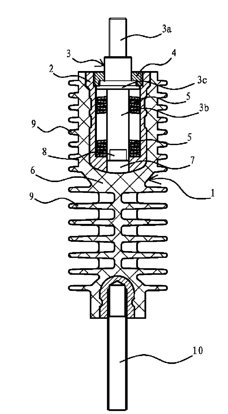
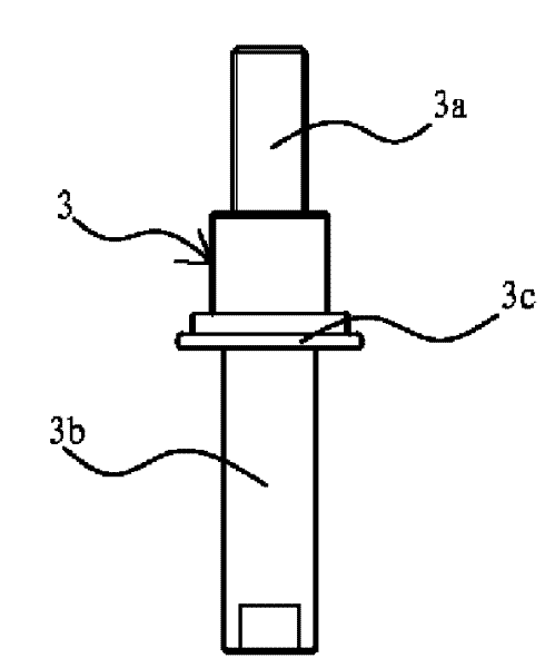
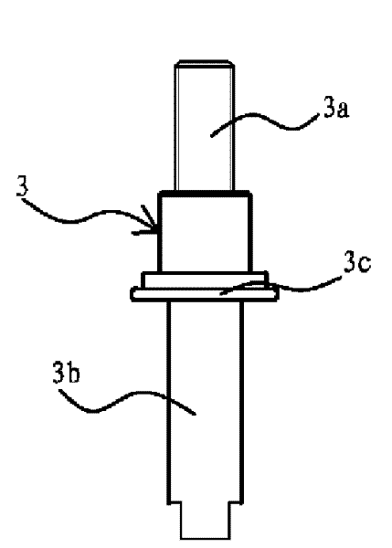
[0040] Such as figure 1 , 2 , 3, 4 and Figure 5 As shown, the insulating pull rod of this circuit breaker is an insulating pull rod 1250A-31.5KA / 3150A-31.5KA suitable for vacuum circuit breakers in 24KV high-voltage switchgear, including connecting rod 3, disc spring 5, spring base 2, rod body 1, and the lower end of rod body 1 A connecting screw 10 is fixedly connected, the spring base 2 is cylindrical and is fixedly connected with the upper end of the rod body 1 , and an outer nut 4 is threadedly connected to the opening at the upper end of the spring base 2 . The connecting rod 3 includes a screw rod 3a and a screw sleeve 3b. The screw sleeve 3b is provided with a retaining edge 3c, which divides the screw sleeve 3b into upper and lower parts. The outer nut 4 is set on the upper part of the screw sleeve 3b and leans against the On the retaining edge 3c, the disc spring 5 is set in the spring base 2 and is sleeved on the lower part of the screw sleeve 3b of the connecting...

Embodiment 2

[0047] Such as Figure 6 , 7 , 8, 9 and Figure 10 As shown, the insulating pull rod of this circuit breaker is a 2000A 31.5KA insulating pull rod suitable for a vacuum circuit breaker in a 40.5KV high-voltage switchgear, including a connecting rod 3, a disc spring 5, a spring base 2 and a rod body 1, and the lower end of the rod body 1 is fixedly connected with a connecting screw. 10. The spring base 2 is cylindrical and fixedly connected to the upper end of the rod body 1 , and the outer nut 4 is threadedly connected to the opening of the upper end of the spring base 2 . The connecting rod 3 includes a screw rod 3a and a screw sleeve 3b. The screw sleeve 3b is provided with a retaining edge 3c, which divides the screw sleeve 3b into upper and lower parts. The outer nut 4 is set on the upper part of the screw sleeve 3b and leans against the On the retaining edge 3c, the disc spring 5 is set in the spring base 2 and is sleeved on the lower part of the screw sleeve 3b of the ...

Embodiment 3

[0054] The difference between this embodiment and Embodiment 1 is that in this embodiment, the circumferential positioning structure between the connecting rod 3 and the spring base 2 is a non-circular stop edge 3c and a stop edge 3c arranged on the spring base 2 A non-circular hole 7 matching the non-circular retaining edge 3c. Other structures are the same as those in Embodiment 1 and will not be described again.


PUM


Abstract

The invention belongs to the technical field of electric devices, and relates to an insulating pull rod for a breaker. The insulating pull rod solves the problem that when a connecting rod in the insulating pull rod of the prior breaker is assembled with a vacuum arc extinguish chamber, the connecting rod rotates and slides. The insulating pull rod of the breaker comprises the connecting rod, a disc spring, a spring pedestal and a rod body, wherein the lower end of the rod body is fixed with a connecting screw; the cylindrical spring pedestal is fixedly connected with the upper end of the rodbody; the upper end of the spring pedestal is fixedly connected with an external nut; the connecting rod is inserted into the spring pedestal; the upper end of the connecting rod passes through the external nut, and extends out of the spring pedestal; the disc spring is arranged in the spring pedestal and sleeved on the connecting rod; two ends of the disc spring act on the spring pedestal and the connecting rod respectively; and a circumferential positioning structure is arranged between the spring pedestal and the connecting rod. The insulating pull rod of the breaker can effectively solve the problems that the connecting rod in the insulating pull rod rotates and slides during assembly, and the insulating pull rod has higher external partial discharge and corona and the like, and simultaneously improves the insulating performance, withstand voltage and mechanical strength of the insulating pull rod.

Description

technical field [0001] The invention belongs to the technical field of electrical devices, and relates to a circuit breaker, in particular to an insulating pull rod of a circuit breaker. Background technique [0002] In the power distribution system, the circuit breaker is a very important part of the power distribution system. Insulation tie rod is an essential accessory on the circuit breaker. The performance of the insulation tie rod will directly affect the withstand voltage performance, insulation performance, breaking performance and operation safety and reliability of the circuit breaker. After using the insulating pull rod, the operation of the circuit breaker will be very convenient. During the use of the insulating pull rod, it is necessary to assemble the insulating pull rod with the vacuum interrupter. [0003] The existing insulating pull rod is mainly composed of a spring base, a connecting rod, an outer nut, and a disc spring, and a round hole and a cylinder ...

Claims


Application Information

Patent Timeline
Patent Type & Authority Patents(China)
IPC IPC(8): H01H33/666
Inventor 张云根
Owner ZHEJIANG ROXZ ELECTRIC CO LTD
Why Eureka
Try Eureka