LED circuit

A technology of LED circuit and LED lamp, which is applied in the direction of circuit layout, lamp circuit layout, electric light source, etc., can solve the problems that cannot be applied independently, and achieve the effect of high reliability, high work efficiency, and corrected power factor

Active Publication Date: 2009-12-09
刘振韬 +1
View PDF0 Cites 9 Cited by
  • Summary
  • Abstract
  • Description
  • Claims
  • Application Information

AI Technical Summary

Problems solved by technology

According to its working mode, it can be roughly divided into the following categories: buck drive circuit BUCK; boost drive circuit BOOST; buck-boost drive circuit BOOST-BUCK, such as: the specific structure is as follows figure 1 Shown; buck-boost drive circuit BBB; buck-boost drive circuit BUCK-BOOST: Although these methods have their own advantages and disadvantages, they have a common feature: the entire drive application circuit contains only one field effect MOSFET, which restricts this application solution to use its boost BOOST and buck BUCK functions at the same time, and cannot be used independently; therefore, they can only maximize their working efficiency when the current output is constant.

Method used


Image

  • LED circuit
  • LED circuit
  • LED circuit

Examples


Embodiment Construction

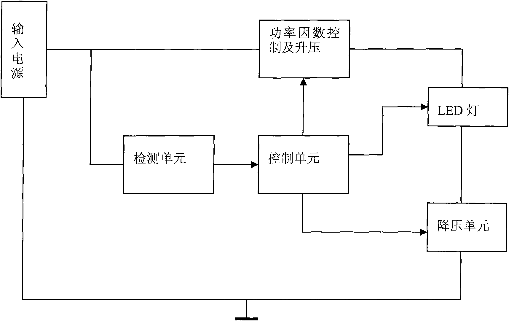
[0017] Such as figure 2 As shown, the LED circuit of the present invention includes:

[0018] Input power to provide working power for each circuit unit;

[0019] Power factor control and boost unit, used to boost and adjust the phase difference between input voltage and loop current;

[0020] LED lights, providing LED lighting;

[0021] A step-down unit, used for step-down, used together with the step-up to stabilize current output;

[0022] The above-mentioned input power supply, power factor control and boost unit, LED lamp and step-down unit form a loop, which also includes:

[0023] A detection unit, connected to the input power supply, for detecting input voltage and loop current;

[0024] The control unit is connected with the detection unit, and controls and connects the power factor control and boost unit, the LED lamp and the voltage drop unit.

[0025] The circuit of the present invention adds a control switch on the basis of the traditional step-up and step-d...


PUM


Abstract

The invention relates to an LED circuit, which comprises a power factor control and voltage boosting unit, an LED lamp, and a voltage reduction unit which are connected in turn, a control unit which is connected with the power factor control and voltage boosting unit, the LED lamp, and the voltage reduction unit, and a detection unit, wherein the power factor control and voltage boosting unit and the voltage reduction unit independently work. On the basis of constant current output, the LED circuit can also adjust the phase difference between input voltage and loop current so as to greatly correct power factors and obtain high work efficiency; and compared with the prior art, the LED circuit has flicker-free adjust luminance, good stability and high reliability.

Description

technical field [0001] The invention relates to digital signal processing, in particular to an LED circuit. Background technique [0002] In today's rapidly developing field of LED application technology, especially in the field of LED lighting technology, whether it is a high-power LED or a small and medium-power LED, considering the work efficiency, the driving circuit generally adopts a constant current switching power supply instead of a linear power supply. According to its working mode, it can be roughly divided into the following categories: buck drive circuit BUCK; boost drive circuit BOOST; buck-boost drive circuit BOOST-BUCK, such as: the specific structure is as follows figure 1 Shown; buck-boost drive circuit BBB; buck-boost drive circuit BUCK-BOOST: Although these methods have their own advantages and disadvantages, they have a common feature: the entire drive application circuit contains only one field effect MOSFET, which restricts this application solution t...

Claims


Application Information

Patent Timeline
Patent Type & Authority Applications(China)
IPC IPC(8): H05B37/00F21V23/00H02M1/42
CPCY02B70/126Y02B70/10
Inventor 刘振韬陈毓霖
Owner 刘振韬
Why Eureka
Try Eureka