

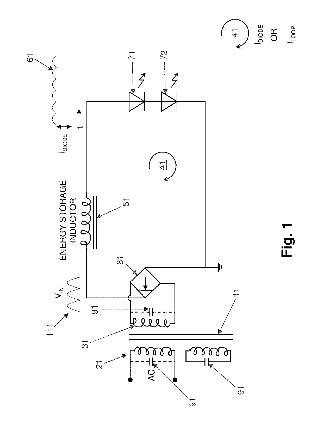
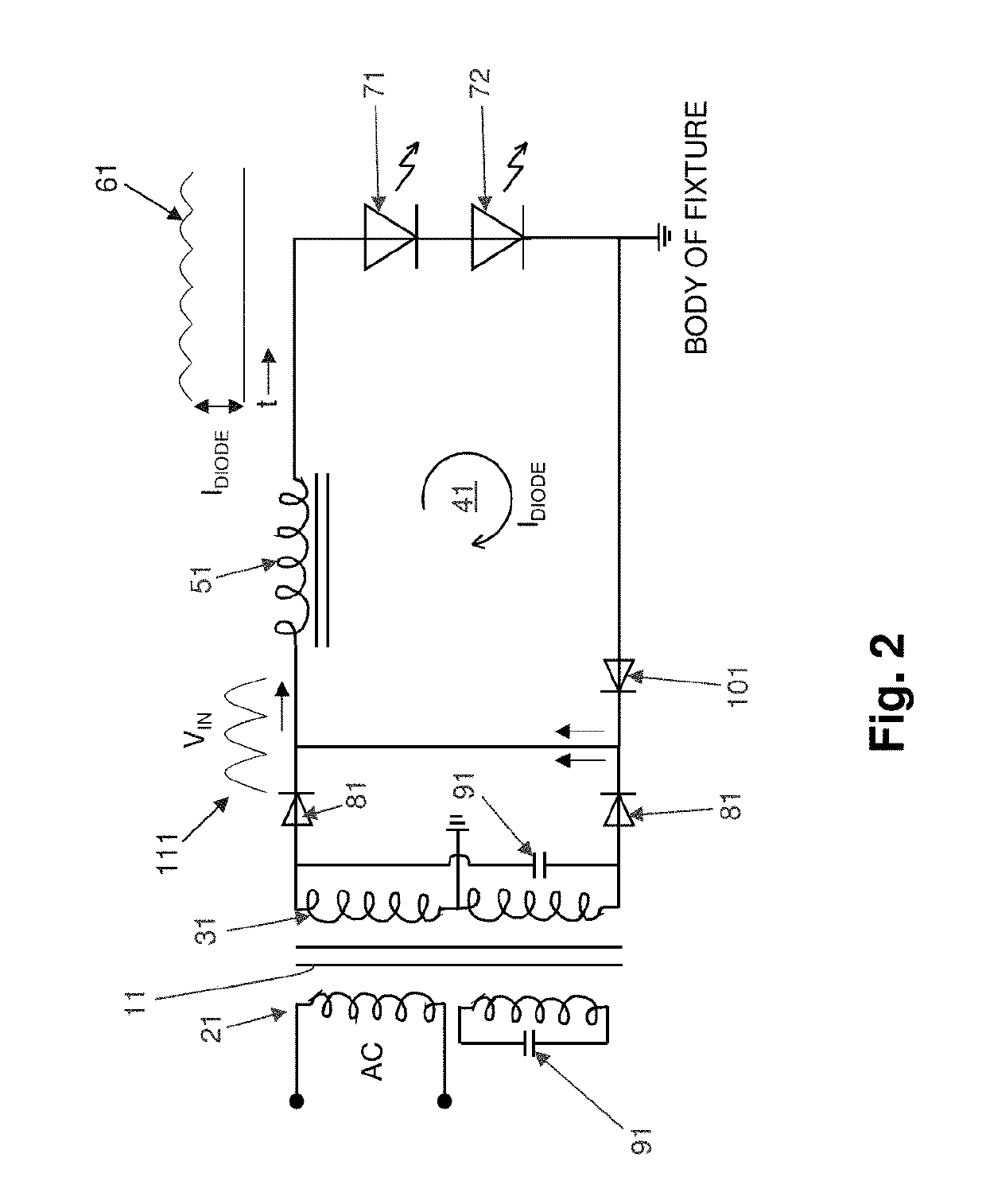
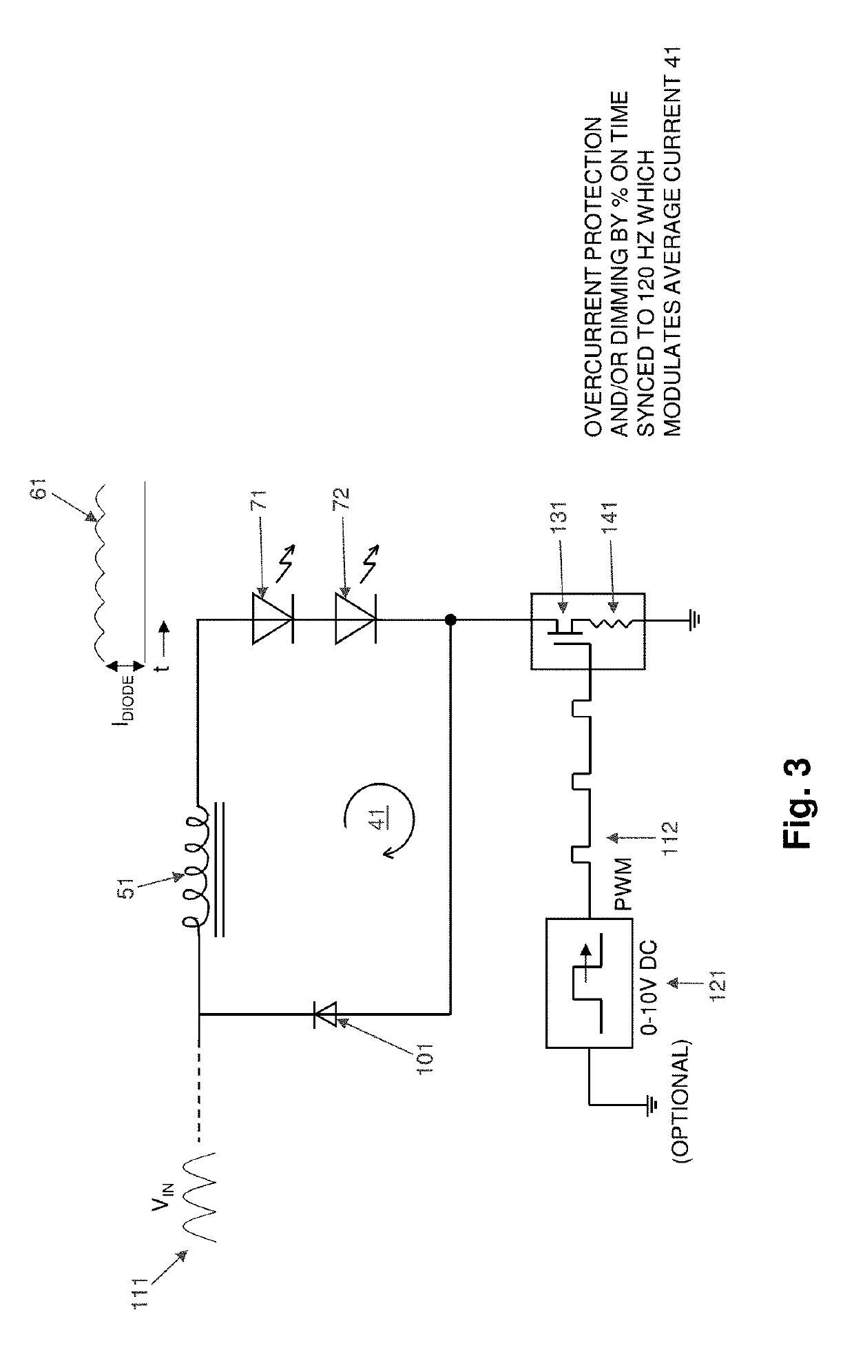
Method of using a high reactance, inductor transformer to passively reduce flickering, correct power factor, control LED current, and eliminate radio frequency interference (RFI) for a current-driven LED lighting array intended for use in streetlight mesh networks
a technology of led lighting array and reactance, applied in the field of large led (light emitting diodes) lighting fixtures, can solve the problems of high cost, large radiation, and difficult operation of high frequency semiconductor switching circuitry over a wide range of input voltages, and achieve the effect of improving power factor and easy heat sinking
- Summary
- Abstract
- Description
- Claims
- Application Information
AI Technical Summary
Benefits of technology
Problems solved by technology
Method used
Image

Examples
Embodiment Construction
[0045]It has occurred to Applicant that, given the lower power requirements of LED lighting, and given the fact that the cost and size of magnetic components (2-3 times larger than the cost and size for non-magnetic components for the same light output) are tolerated in the millions of gas-discharge lamps (of 175 to 400 watt size) currently in use, a high-volume-production, magnetic component, rated at only 40% of the current KVA size, may be used without incurring prohibitive cost issues. This is especially true when considering the costs associated with (i) all of the capacitors and power electronic components required for the high frequency “switcher” type LED lighting, (ii) required heat-sinking of the semiconductor components of the LED lighting, (iii) preventing those components from radiating RFI, (iv) the surge suppression required to properly protect a high frequency, all-electronic “switcher” approach from 4 KV transients of high power, and (v) insulating the LEDs for long...
PUM
| Property | Measurement | Unit |
|---|---|---|
| magnetic energy | aaaaa | aaaaa |
| magnetic energy | aaaaa | aaaaa |
| power | aaaaa | aaaaa |
Abstract
Description
Claims
Application Information