Wire rope flaw detector
A flaw detection device, wire rope technology, used in transportation and packaging, material magnetic variables, electromagnets, etc.
- Summary
- Abstract
- Description
- Claims
- Application Information
AI Technical Summary
Problems solved by technology
Method used
Image
Examples
Embodiment approach 1
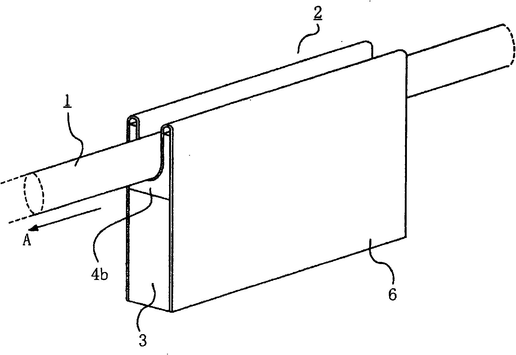
figure 1 It is a perspective view showing the wire rope flaw detection device according to Embodiment 1 of the present invention. exist figure 1 Among them, the wire rope flaw detection device 2 has a guide plate 6 having a substantially U-shaped guide groove 6a through which the wire rope 1 moves (direction A in the drawing). The wire rope flaw detection device 2 includes a magnetizer that forms a main magnetic circuit in a predetermined section in the axial direction of the wire rope 1 , and a leakage flux detector that detects a leakage flux generated by a damaged portion of the wire rope 1 .
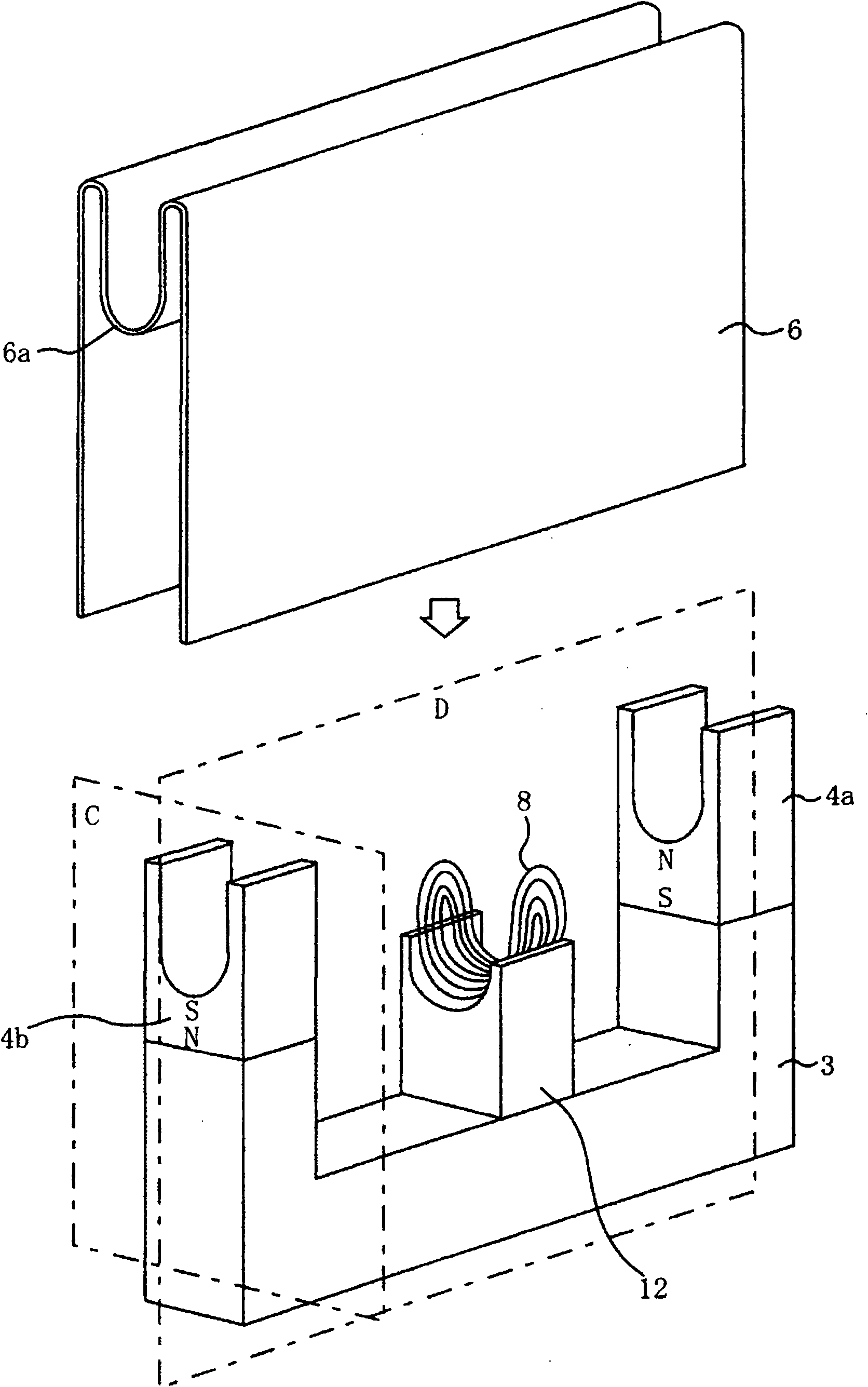
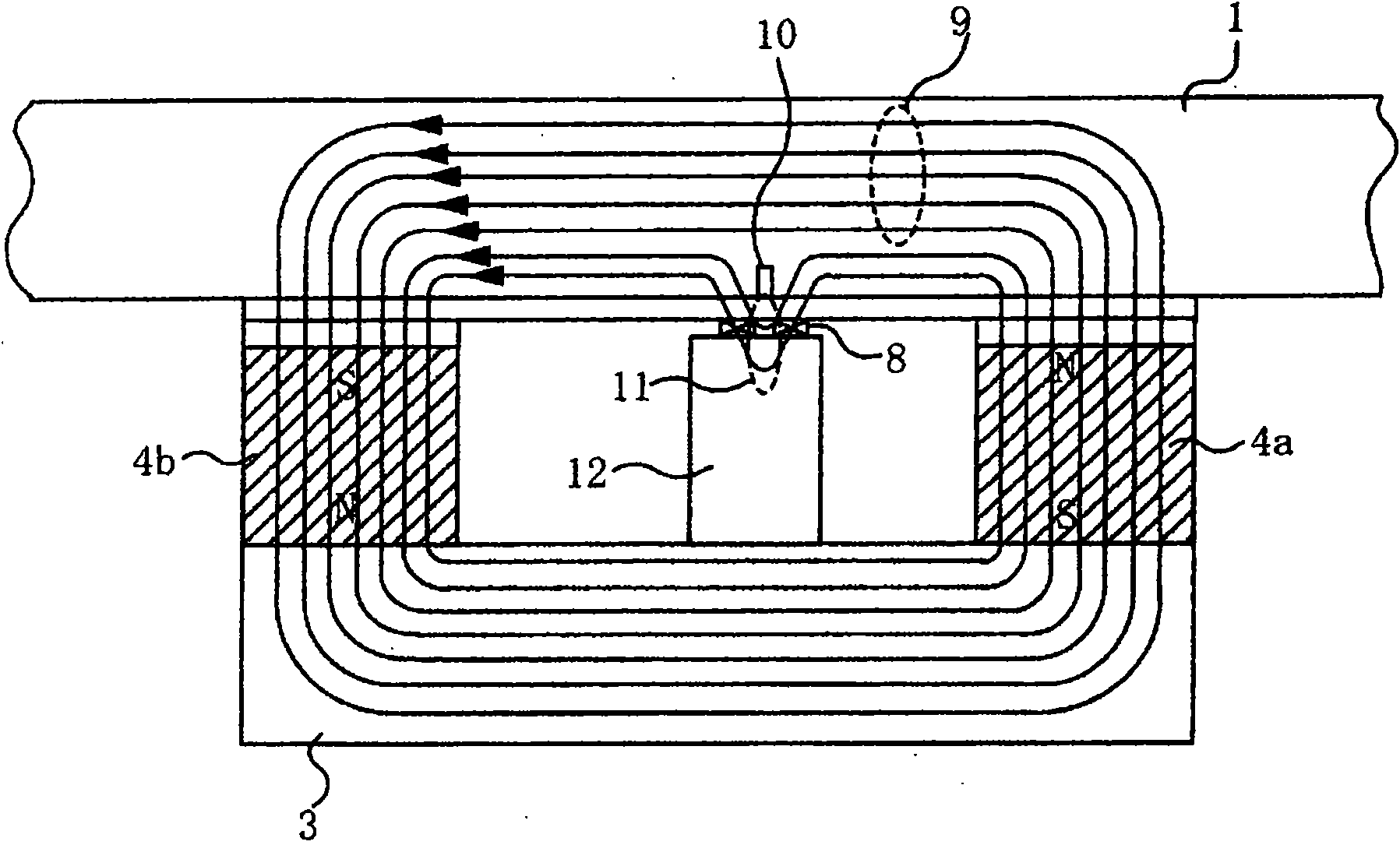
[0012] figure 2 to represent figure 1 A perspective view of the state of the wire rope flaw detection device with the guide plate removed. The magnetizer of the steel wire rope flaw detection device 2 is used to form the main magnetic circuit in the axially specified section of the steel wire rope 1, and has a rear yoke 3 and a pair of permanent magnets 4a and 4b for excitatio...
Embodiment approach 2
Figure 24 It is a perspective view showing a permanent magnet for a field according to Embodiment 2 of the present invention, Figure 25 For cutting with a plane perpendicular to the axial direction of the wire rope Figure 24 Cross-sectional view of a permanent magnet for excitation. In the structure of the permanent magnet for field excitation according to Embodiment 2, the magnetic pole piece 5 is bonded to a block-shaped permanent magnet 60 with a length of 15 mm, a width of 15 mm, and a height of 15 mm. The cross-section of the sheet 5 cut along a plane perpendicular to the axial direction of the wire rope has a substantially U-shape. On the block-shaped permanent magnet 60, plate-shaped auxiliary permanent magnets 16a, 16b of length 15 mm, width 2.5 mm, and height 10 mm are arranged on the side surfaces of the U-shaped cross-section pole piece 5 so that the polarities face each other. Such as Figure 25 As shown, the orientation directions of the magnetic poles of th...
Embodiment approach 3
Figure 28 and Figure 29 It is a perspective view showing a state in which a guide plate is removed of the wire rope flaw detection device according to Embodiment 3 of the present invention. Figure 30 It is a cross-sectional view of the permanent magnet for excitation of the wire rope flaw detection device according to Embodiment 3 of the present invention.
[0040] The steel wire rope flaw detection device of Embodiment 3, by combining Figure 28 as shown in the 1st device and Figure 29 The second device as shown is formed; the first device includes the rear yoke 3, the first field permanent magnets 4a and 4b having arc shapes in the cross-section cut by a plane perpendicular to the axial direction of the steel wire rope, and Detection coil 8 and guide plate 6 on the base 12; the second device includes a rear yoke 3, a second excitation permanent magnet 4c with an arc shape in a cross-section cut on a plane perpendicular to the axial direction of the wire rope And 4d, g...
PUM
| Property | Measurement | Unit |
|---|---|---|
| The average particle size | aaaaa | aaaaa |
Abstract
Description
Claims
Application Information
 - R&D
- Intellectual Property
- Life Sciences
- Materials
- Tech Scout
- Unparalleled Data Quality
- Higher Quality Content
- 60% Fewer Hallucinations
Browse by: Latest US Patents, China's latest patents, Technical Efficacy Thesaurus, Application Domain, Technology Topic, Popular Technical Reports.
© 2025 PatSnap. All rights reserved.Legal|Privacy policy|Modern Slavery Act Transparency Statement|Sitemap|About US| Contact US: help@patsnap.com


