Active core current sensor

a current sensor and active core technology, applied in the field of current sensors, can solve the problems of inability of current transformers and rogowski coils to operate to sense direct currents, and the inability to reliably detect current in conventional sensing circuits, and achieve the effect of high permeability materials

Inactive Publication Date: 2012-08-02
ROCKWELL AUTOMATION TECH
View PDF3 Cites 11 Cited by
  • Summary
  • Abstract
  • Description
  • Claims
  • Application Information

AI Technical Summary

Benefits of technology

[0007]The present invention provides a novel current sensing technique designed to respond to such needs. The technique makes use of a closed magnetic path in a core, such as a high permeability material. Accuracy is maintained in the presence of foreign magnetic and electromagnetic fields, such as those of adjacent conductors. The technique may be used to measure both alternating and direct currents, and higher currents (that tend to saturate the sensing circuit core). Moreover, with little change, hardware used in the technique can be adapted to selectively operate in one manner for sensing lower currents, and in a different manner (disclosed below) for higher currents. The techniques may be used in a wide range of applications, such as microprocessor and DSP based systems. Presently contemplated applications include variable speed motor drives and other power electronic and power delivery solutions.
[0008]Briefly, according to certain embodiments of the invention, a method for sensing current through a conductor is provided. The method comprises switching a control circuit to allow a primary current through the conductor to create a flux in a closed core of a sensing coil, including flux levels that saturate the core. The control circuit is then switched to alter the flux, and a value representative of current through the sensing coil is sensed while the flux is altered. If the core is saturated, the flux may be reduced (or more generally, altered) to a level that will draw the core out of saturation to a non-saturated region, such as to a linear range of a BH hysteresis loop of the core. The value is then transformed to create a measurement of the current through the conductor.
[0009]In another embodiment, a system for sensing current through a conductor is provided. The system comprises a sensing coil wound around a closed core configured to receive the conductor therethrough, and control circuitry coupled to the sensing coil and comprising at least one switch. The control circuitry is configured to place the switch in a first conductive state to allow primary current through the conductor to create a flux in the core, including flux levels that saturate the core. The conductive state of the switch is then changed to alter the flux, such as to draw the core out of saturation if it is saturated. The system further includes measurement circuitry coupled to the control circuitry and configured to generate a signal representative of current through the sensing coil.

Problems solved by technology

While such arrangements provide excellent options in many applications, they are not without drawbacks.
For example, current transformers and Rogowski coils generally cannot operate to sense direct currents.
Moreover, for higher currents, the cores of current transformers may saturate, rendering reliable sensing of current by conventional sensing circuits impossible.
Hall effect sensors, on the other hand, may be susceptible to the effects of outside or foreign fields due to the gap in the sensing core where the semiconductive device is placed.
Also, depending upon the current levels and components selected, such sensors may be more expensive than current transformers.

Method used


Image

  • Active core current sensor
  • Active core current sensor
  • Active core current sensor

Examples


Embodiment Construction

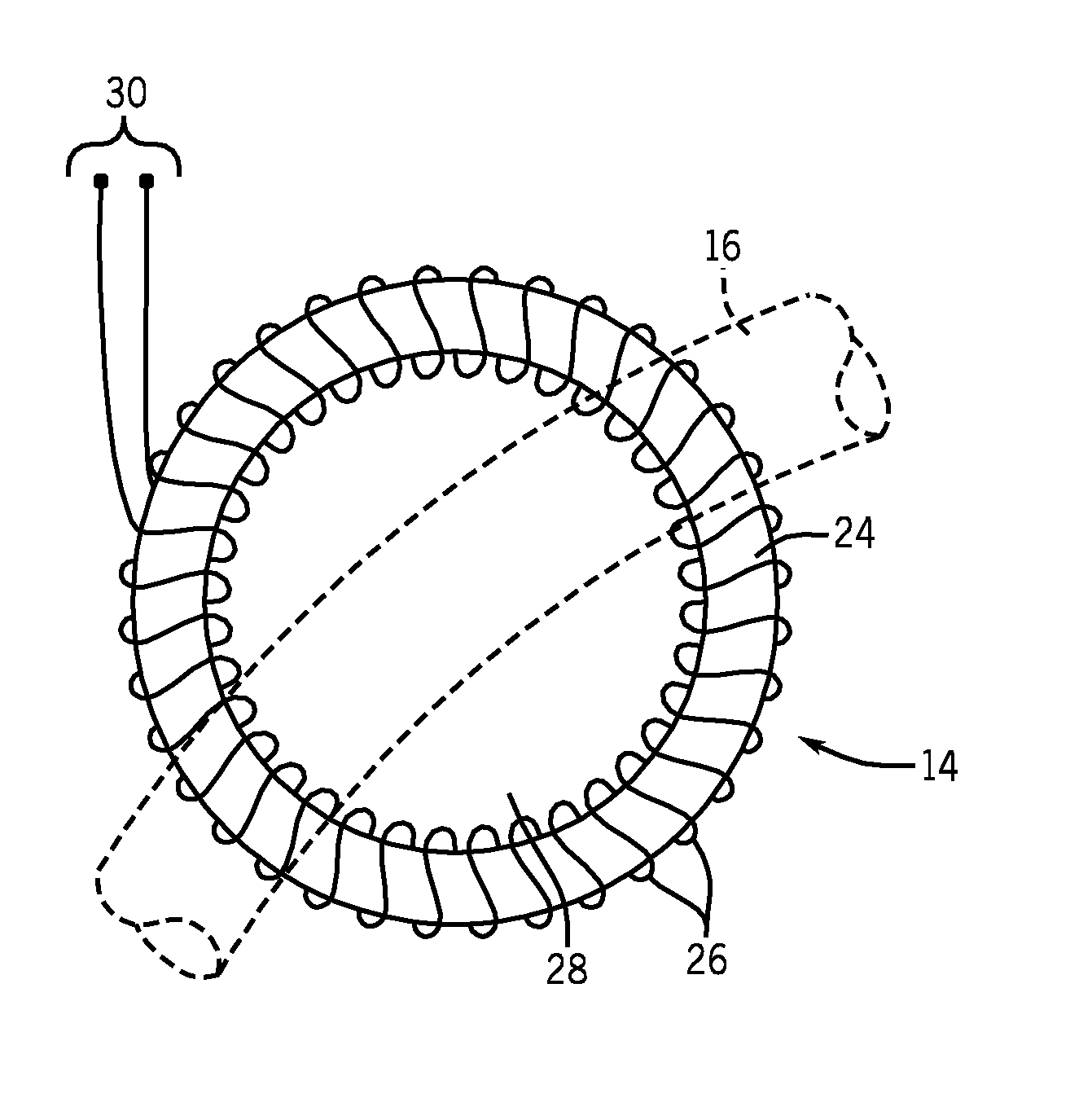
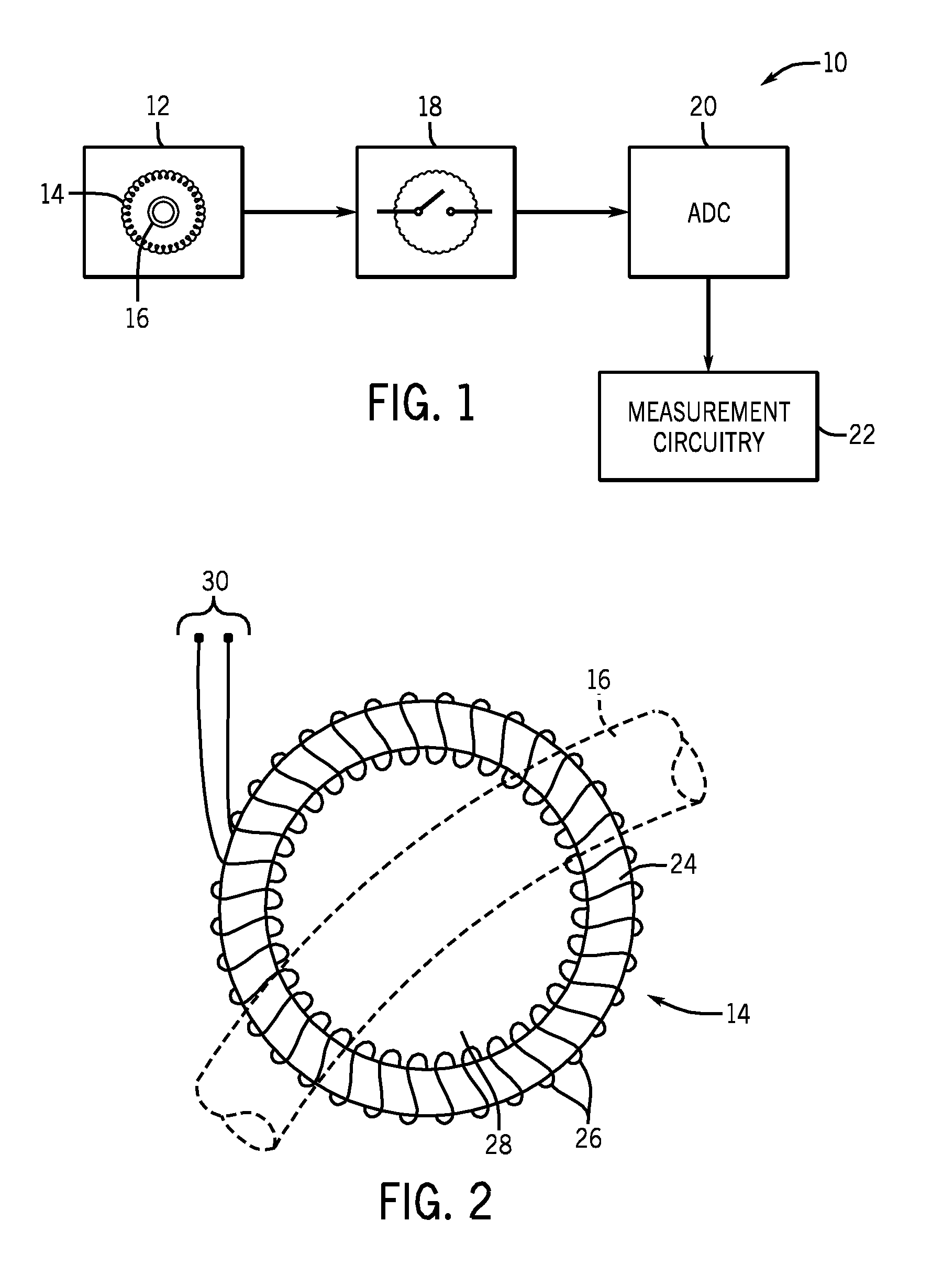
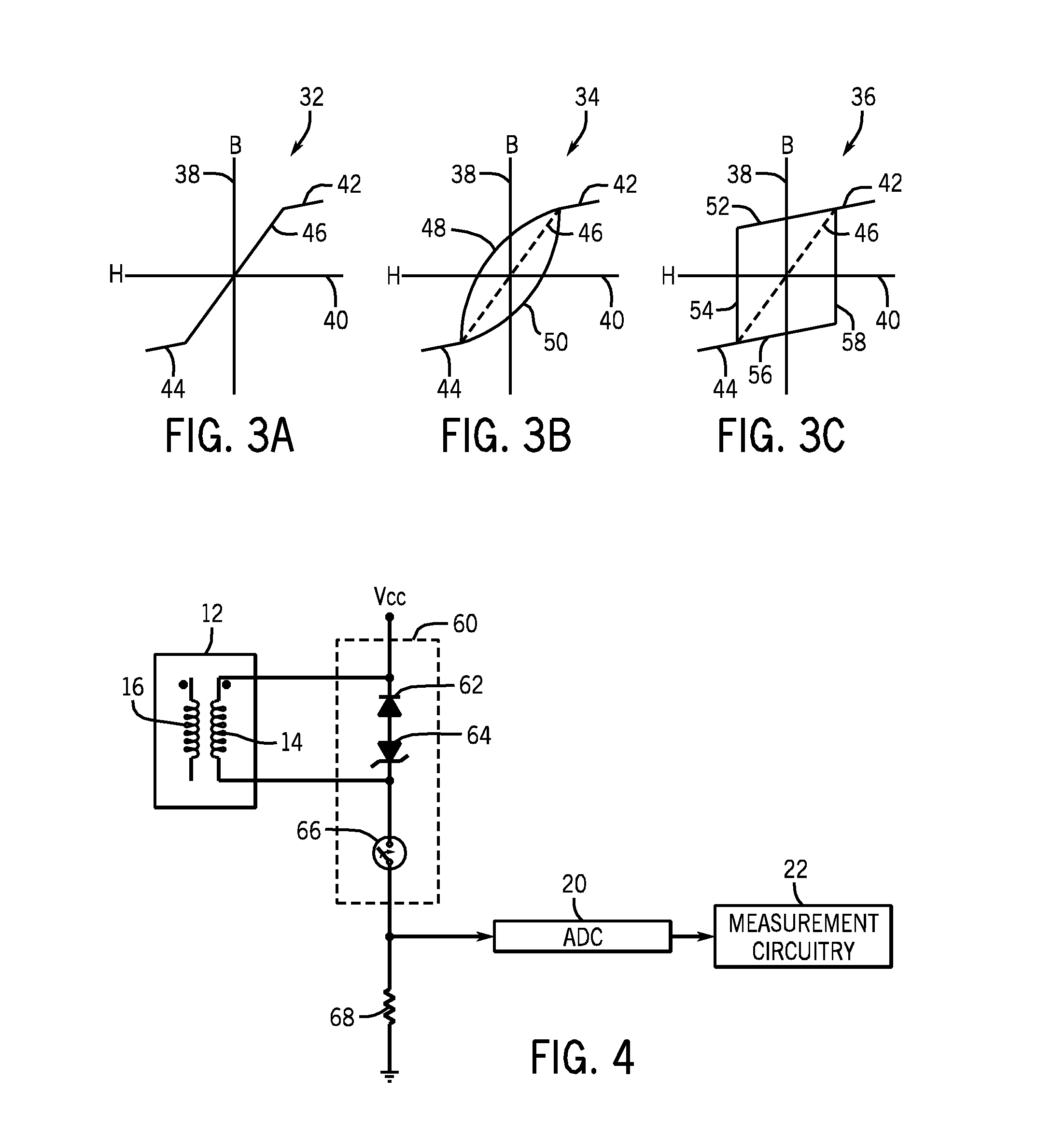
[0021]The technique disclosed below allows for sensing currents in a transformer-type sensing arrangement that includes a closed magnetic core, which may be made of a high permeability material. The technique samples current in a secondary circuit normally when the core is not saturated (which may be in a linear region of the BH hysteresis loop of the core), and by driving the core to a non-saturated region of a BH hysteresis loop of the core when the core is saturated (which may again be in a linear region of the hysteresis loop). This in turn causes the secondary current to flow that is proportional to the primary current by a turns ratio of the transformer. A power source may be used to supply the secondary current since the core flux is driven in an opposite direction with regard to the flux induced by the primary current. In situations where the core saturates, the output signal is available only during the time when the core flux density is in a non-saturated range of the BH h...


PUM


Abstract

Methods and system for sensing current include detecting current through a sensing coil resulting from a field produced by current through a primary conductor. The sensing coil has a core that may become saturated by the primary current field. If the core is not saturated, a sensing circuit may detect the current through the sensing coil by changing the state of at least one controlled switch. If the core is saturated, the sensing circuit changes the state of the at least one controlled switch to pull the core out of saturation, at which time a current measurement is made. The technique may be used with AC currents, including changing currents, as well as with DC currents, and currents that may be AC at times and become essentially DC at other times.

Description

BACKGROUND[0001]The invention relates to current sensors, and more specifically to a system and method for sensing current by allowing saturation of a core element and drawing the element out of saturation for current measurements.[0002]Many different types and designs of current sensors have been developed and are commercially available. In certain current sensing circuits, a sensing coil is placed within a flux field of a conductor through which the current to be sensed flows. The flux, proportional to the flowing current, induces a current or a voltage in the sensing coil. A voltage across a burden resistor associated with the sensing coil can then be measured, and used as a basis for calculating the current in the conductor, the induced current being a function of the number of turns of the sensing coil. Such devices effectively define transformers in which the conductor (or conductors) forms the primary, and the sensing coil forms the secondary.[0003]Other arrangements are avai...

Claims


Application Information

Patent Timeline
Patent Type & Authority Applications(United States)
IPC IPC(8): G01R15/18
CPCG01R15/185
Inventor BLAKELY, JOHN HERMAN
Owner ROCKWELL AUTOMATION TECH
Why Eureka
Try Eureka