
Magnetic communication through metal barriers

a metal barrier and magnetic communication technology, applied in the field of wireless communication, can solve the problems of inability to use traditional wireless data communications technologies in most applications, inability to work in most applications, and blockage or heavy attenuation of rf signals, so as to increase data security and data-rate communications. the effect of communication

Inactive Publication Date: 2008-03-20
HYDROTECH A CALIFORNIA
View PDF18 Cites 59 Cited by
  • Summary
  • Abstract
  • Description
  • Claims
  • Application Information

AI Technical Summary

Benefits of technology

[0015] Benefits and advantages of the present invention include, but are not limited to, higher data-rate communications through materials than are available using present acoustic techniques, the ability to transfer data and power, increased data security, and the ability to penetrate a wide variety of media.

Problems solved by technology

In many underwater applications it is impractical or unsafe to penetrate a pressure hull with wire penetrators for communications purposes.
Additionally, traditional wireless data communications technologies will not work in most of these applications due to the hull construction.
The conductive nature of these hull materials results in the blockage or heavy attenuation of RF signals.
However, acoustic communications through thick metal barriers has been found to be problematic.
The most significant of difficulty includes multi-path propagation, where many “echoes” of the intended signal are generated, thereby increasing the system noise and limiting useful bandwidth.
Multi-modal propagation of sound through various materials can also cause signal distortion.
In addition, acoustic signals when used for this type of communication can result in a detectable acoustic signature which is undesirable for many applications.

Method used


Image

  • Magnetic communication through metal barriers
  • Magnetic communication through metal barriers
  • Magnetic communication through metal barriers

Examples


example 1

[0037]FIG. 5 is a graph of the response of the present apparatus defined as the ratio of the output voltage to the input voltage (upper curve), as a function of frequency for a 0.875″ thick, grounded slab of stainless steel. A signal voltage of 12 V rms and 0.145 A rms (1.43 W total power), was found to provide good signals in the receiver coil. A 3″ thick metallic barrier of similar material to that used as the pressure hull of Los Angeles class submarines was also shown to allow magnetic field transmission. The lower curve of FIG. 5 represents the noise floor for the apparatus employed.

example 2

[0038]FIG. 6 is a graph of the response of the present apparatus defined as the ratio of the output voltage to the input voltage (upper curve), as a function of frequency for a 0.125″ thick, grounded slab of 5086 aluminum. The lower curve of FIG. 7 represents the noise floor for the apparatus employed.

example 3

[0039]FIG. 7 is a graph of the response of the present apparatus defined as the ratio of the output voltage to the input voltage (upper curve), as a function of frequency for a grounded, 0.45″ thick slab of glass fiber reinforced polymer comprising three approximately equal thickness layers. It is believed by the present inventors that the increase in response at higher frequencies is likely an artifact of the measurement apparatus. The lower curve of FIG. 7 represents the noise floor for the apparatus employed.


PUM


Abstract

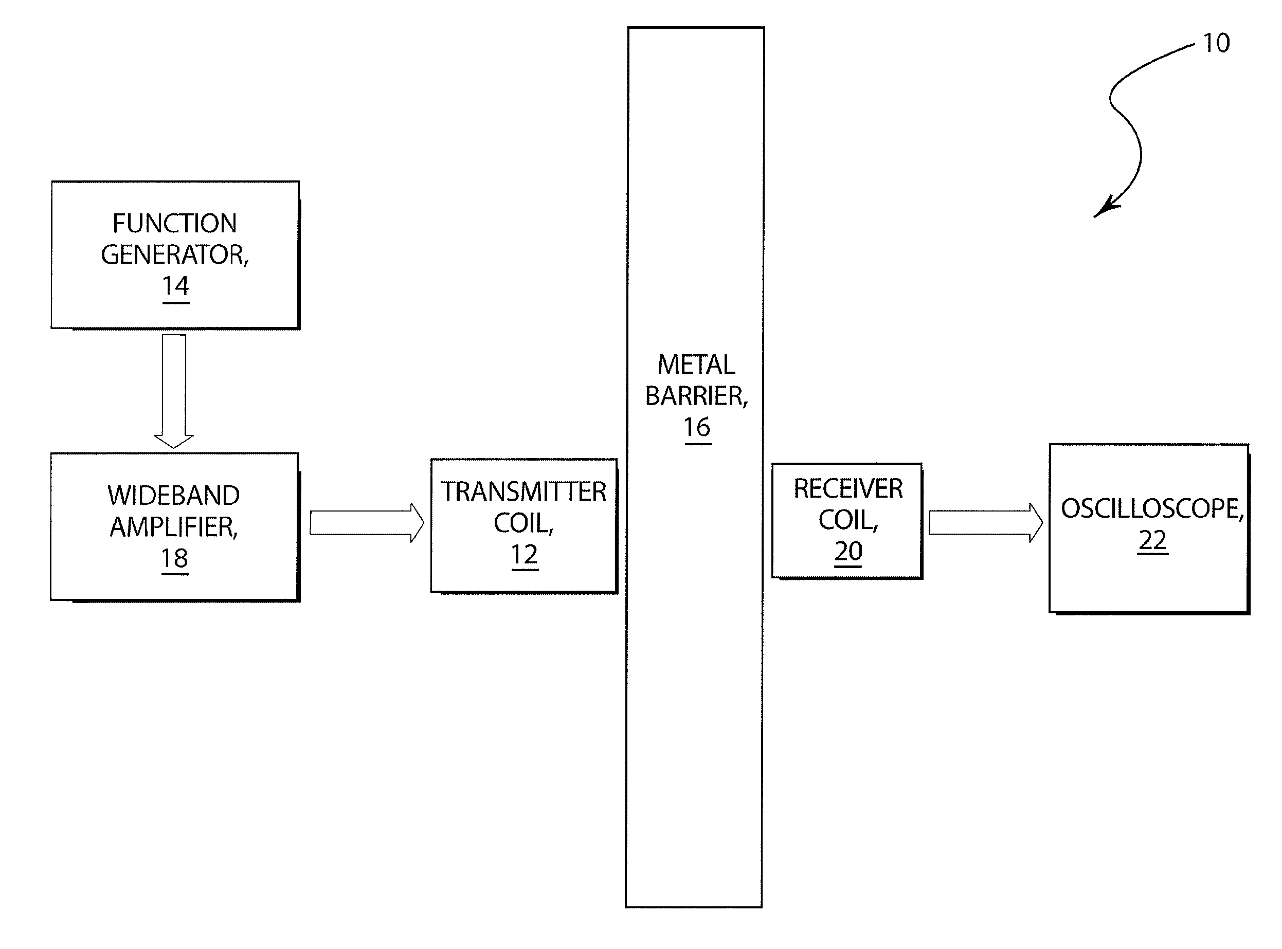
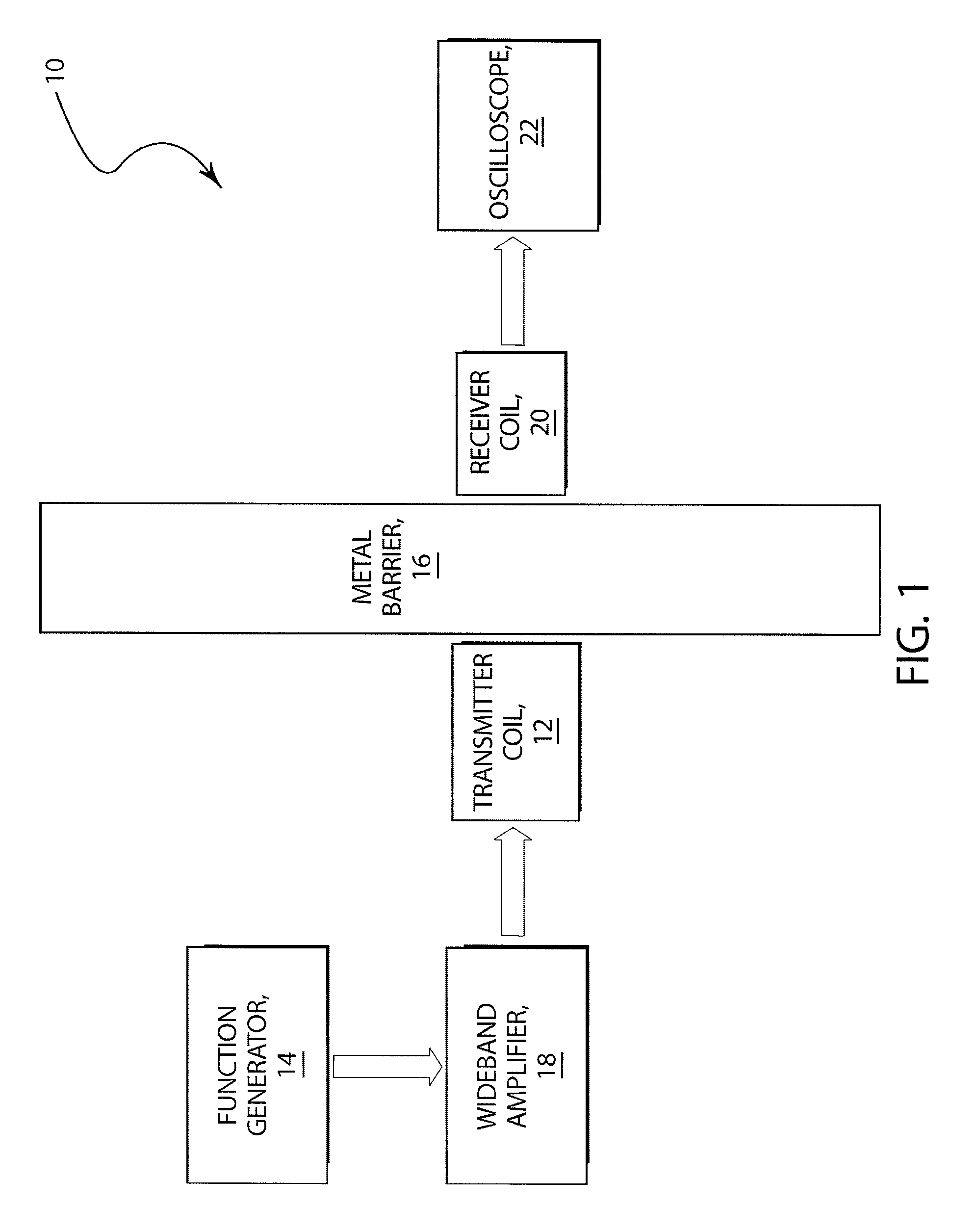
A wireless magnetic through-hull communications apparatus and method which permit higher data-rate communications through materials than presently available using acoustic techniques is described. A signal source on one side of a barrier is directed into a coil driver which generates an amplified, modulated signal responsive thereto. The resulting signal is used to drive a transmitter coil which generates a time-varying magnetic field that penetrates the barrier as well as any gaps comprising water, air or other material between the barrier and the transmitter coil. On the other side of the barrier, and perhaps through additional gaps comprising water, air or other material, a receiver coil detects the time-varying magnetic field. This signal may be amplified and then digitized by a signal processor. The signal processor may then communicate with a data processing and / or display unit, another sensor or some other device. Electric power may also be transmitted through the barrier for providing power to instrumentation without the need for batteries.

Description

RELATED CASES [0001] The present patent application claims the benefit of Provisional Patent Application Ser. No. 60 / 826,200 filed on Sep. 19, 2006 entitled “Magnetic Communication Through Metal Barriers” by Corey J. Jaskolski et al. which application is hereby incorporated by reference herein for all that it discloses and teaches.FIELD OF THE INVENTION [0002] The present invention relates generally to wireless communication and, more particularly, to wireless communications through metal barriers using magnetic fields. BACKGROUND OF THE INVENTION [0003] Most wireless communication is achieved using RF plane waves propagated through space. Communication using wireless magnetic fields has been accomplished using a non-propagating magnetic field upon which signals are impressed, and which is approximately localized around the transmitting device. The information contained in the signals is transmitted through a medium and received by a remote transducer using the principle of magnetic...

Claims


Application Information

Patent Timeline
IPC IPC(8): H04B5/00
CPCH04B5/00H04B5/0031H04B5/0093H04B5/0075H04B5/0037H04B5/266H04B5/24H04B5/72H04B5/79H04B13/02
Inventor WILHELM, GRAHAM R.JASKOLSKI, COREYBERKENPAS, ERIC
Owner HYDROTECH A CALIFORNIA
Learn More