Bone cement injection device

a technology of bone cement and injection device, which is applied in the field of bone cement injection device, can solve the problems of reducing the pain experienced by patients, affecting the quality of bone cement injection, and the transpedicular vertebroplasty procedure itself has not been optimized to date, and achieves the effect of high viscosity material

Inactive Publication Date: 2011-06-30
STEFFEN THOMAS +2
View PDF46 Cites 53 Cited by
  • Summary
  • Abstract
  • Description
  • Claims
  • Application Information

AI Technical Summary

Benefits of technology

[0011]It is therefore an aim of the present invention to provide an improved system and / or method for injecting high viscosity material, such as bone cement.

Problems solved by technology

The gradual loss of bone minerals and progressive structural change of the trabecular bone which occur in osteoporosis result in vertebral fragility fractures.
The bone cement, once hardened, becomes a permanent reinforcement of the vertebral body and usually drastically diminishes the pain experienced by the patient.
As a result, the transpedicular vertebroplasty procedure itself has not to date been optimized, such as to improve the ease of performing this surgical procedure while reducing the risk to both patient and surgeon.
For example, one risk inherent with the transpedicular vertebroplasty is the potential for bone cement leakage out of the vertebral body and into the venous system or into the spinal canal, which can cause serious, life threatening complications.
The inherent disadvantage of such smaller syringes is that many are required to inject the recommended amount of cement into a single vertebral body (typically 6-8 cc in the lumbar region, maximum 10 cc).
Also, small syringes lack the volumetric stiffness and strength of components (e.g., the plunger) to handle sufficiently high pressures (3-5 MPa and higher).
The use of several small syringes is therefore time consuming and less than ideal.
Filling and using multiple syringes requires the clinician to repeatedly change syringes, which can distract attention away from the procedure at hand and any potentially dangerous complications which may occur, such as leakage of the cement for example.
Still other disadvantages of working with multiple small syringes are that the procedure is time consuming, messy, and filling multiple small syringes ahead of time with cement may cause the syringe nozzle to clog.
For example, some such devices are large and bulky, and employ large hand lever pumps or power screws to displace the cement.
The significant weight and bulk of such devices makes them less practical and unsuitable for mounting directly atop a bone biopsy cannula, because the weight may bend the cannula and fracture the osteoporotic pedicle.
Unfortunately, the friction of the cement flowing through such a long small diameter tube is extremely high and, as a result, almost all of the force generated by the gun, pump or power screw is used to overcome this friction within the piping.
Further, these large systems dramatically limit the tactile feel of the surgeon and their sheer size become very cumbersome and expensive when three or four units are required for use simultaneously, such as during a multi-segmental procedure.
Another challenge facing surgeons performing vertebroplasty is the determination of when the bone cement is ready to be injected into the vertebral body.
This method is clearly subjective, and further the sample taken may not be representative of the remaining cement in the injector, which may potentially be polymerizing at a different rate depending on a number of factors, including for example the thermal transfer properties of the reservoir material, room temperature and humidity, and the heat transferred from the hand of the surgeon to the sample as it is mechanically massaged.

Method used


Image

  • Bone cement injection device
  • Bone cement injection device
  • Bone cement injection device

Examples


Embodiment Construction

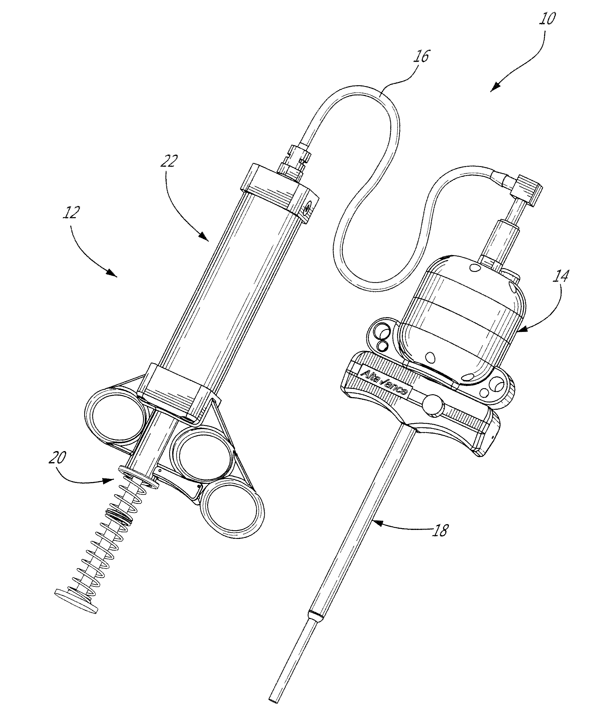
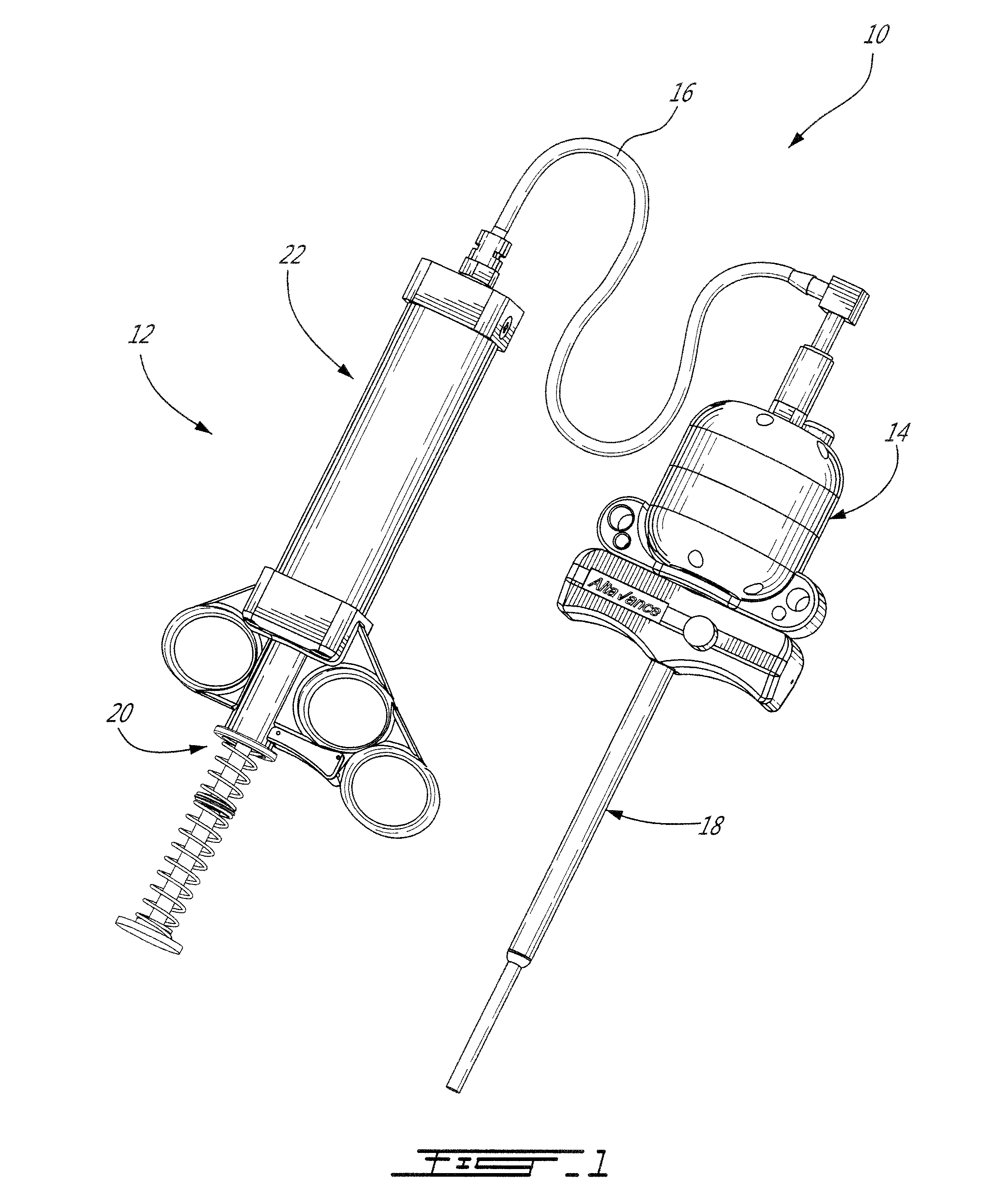
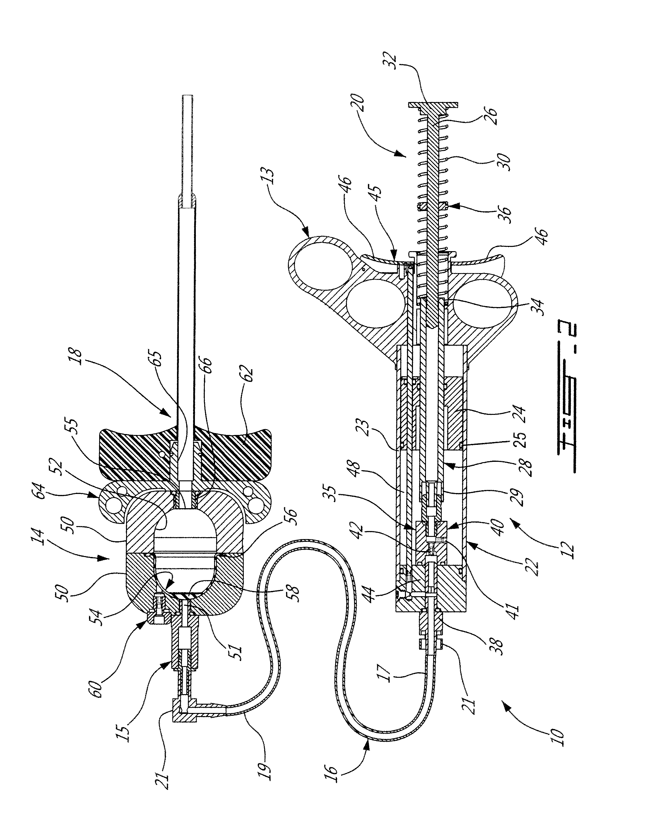
[0041]The present injection system is preferably adapted for, and used to perform, percutaneous vertebroplasty and more particularly transpedicular vertebroplasty. However, the present system may also be adapted for other medical uses which involve injecting high viscosity material, either bone cement or otherwise, into a cavities, especially intraosseous ones.

[0042]Using the present injection system as described below, the vertebral body is filled with bone cement, such as Polymethyl Methacrylate [PMMA] for example, via a cannula and solidifies in and thus stabilizes the fractured vertebra. The cannula is inserted through the cutaneous layers and the cortical bone of the vertebra so that the tip of the cannula can be positioned transpedicularly in the cancellous bone of the vertebral body. The high viscosity bone cement is then able to be delivered through the cannula, usually under fluoroscopic guidance, into the trabecular bone of the vertebral body. By injecting the bone cement ...


PUM


Abstract

A system for injecting an incompressible low viscosity fluid into a bone cement reservoir adapted to be engaged with a cannula through which a high viscosity bone cement is transferred from the bone cement reservoir to a bone element is provided. The system comprises a control handle having a cylindrical body, a grip portion at an outer end of the cylindrical body and a central thumb-actuated plunger of a power piston, the grip portion being configured for receiving at least two fingers a user such as to permit actuation of the control handle by the single hand of the user, the cylindrical body including the power piston and a low viscosity fluid reservoir concentrically disposed relative to each other, the low viscosity fluid reservoir containing the incompressible low viscosity fluid and the power piston extending longitudinally through a center of the low viscosity fluid reservoir.

Description

CROSS-REFERENCE TO RELATED APPLICATIONS[0001]The present application is a continuation of Intentional Patent Application No. PCT / CA2009 / 001002 filed Jul. 15, 2009, which claims priority on U.S. Provisional Patent Application No. 61 / 080,808 filed Jul. 15, 2008, the entire contents of both of which are incorporated herein by reference.TECHNICAL FIELD[0002]The present invention relates to the field of injection biomechanics, and more particularly to a system for injecting a high viscosity material, such as bone cement, to a bone site, for example vertebral bodies.BACKGROUND OF THE ART[0003]Percutaneous vertebroplasty is now commonly used to repair vertebrae which have become damaged or weakened, for example by osteoporosis, osteolytic spinal tumours, and the like. The gradual loss of bone minerals and progressive structural change of the trabecular bone which occur in osteoporosis result in vertebral fragility fractures. Vertebroplasty is used to improve the structural integrity of suc...

Claims


Application Information

Patent Timeline
Patent Type & Authority Applications(United States)
IPC IPC(8): A61B17/58
CPCA61B17/8827A61B17/8822
Inventor STEFFEN, THOMASBECKMAN, LORNEGIANNITSIOS, DEMETRIOS
Owner STEFFEN THOMAS
Why Eureka
Try Eureka